Function, Figure 4, Schematic diagram of functioning of heat exchanger – M&C TechGroup ECS Operator's manual User Manual
Page 12
12
Gas sampling and gas conditioning technology
3-4.1-ME
10
FUNCTION
The M&C EC/ECS gas cooler is a compressor cooler with status alarm capability. This ensures 100%
availability of the cooler.
Up to 4 Jet-stream heat exchangers made of Duran glass, PVDF or stainless steel are located in a
heat-insulated cooling block. All the heat exchangers are easily accessible and are arranged in such a
way that they can be removed very simply.
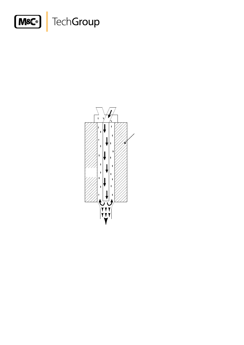
Figure 3 shows a schematic diagram of the functioning of the heat exchanger..
+5°C
Sample gas
out
Sample gas
in
Condensate out
Cooling-
block
Figure 4 Schematic diagram of functioning of heat exchanger
The compressor cooler system has a heat-insulated cooling block at a constant temperature of +5°C.
Control of the compressor for models as from serial numbers 95... is done contactless by the EC
automatic control electronics and is therefore not subject to wear.
The novel construction of the heat exchanger guarantees a very good pre-separation of condensate
and for that reason an optimal drying of sample gas.
Alarm warnings for excess- and low-temperature are given as a collective status alarm via a relay
output with two potential-free changeover contacts. Alarm will be released if the current temperature
is out of a range of
3°C referring to the set-temperature (+5°C) .