Figure 3 – M&C TechGroup ECS Operator's manual User Manual
Page 11
11
Gas sampling and gas conditioning technology
3-4.1-ME
The EC/ECS
is equally suitable for wall installation or mounting in a 19“-rack.
The versions differ in the positioning of the LED function display . While for wall installation the LED
function display can be fitted into the corresponding cut-outs in the EC/ECS
front panel, for 19”
rack mounting this is done using the cut-outs in the back panel of the casing. This positioning can be
done at the factory when stating the type of installation of the EC/ECS gas cooler. It is relatively
simple to subsequently reconfigure it on site at the user location. The location for installation of the
LED function display will be marked correspondingly.
The casing depth of the EC-.. cooler is 450mm. The ECS cooler unit differs in its less casing depth of
360mm and thereby is appropriate for mounting in a gas analysis cabinet with swing frame.
On the upper side of the cooler casing you will see the cut-outs for maximum 4 heat exchangers.
Sample gas enters and leaves the heat exchangers by the correspondingly connections on the upper
part of the heat exchangers.
At the rear part of the casing the condenser to remove heat given off in the compressor can be
seen.
The EC automatic control board is located in the plastic housing behind the removable front panel
of the EC/ECS casing.
On the underside of the casing the following connections are provided as standard:
Standard condensate outlets from the heat exchangers respectively,
Cable glands PG 13,5;
As standard, the condensate is removed externally with collecting vessels, peristaltic pumps SR25.1,
or by “over-pressure operation”, with automatic drawing-off of condensate, as e.g. type AD-... .
The heat energy from the cooling system is drawn off by a forced-ventilation . The required fans
and large air suction filter elements are provided as standard in This is arranged below the EC/ECS
casing and is absolutely essential for operation of the cooler unit.
Optionally, the automatic condensate removal unit EC-FD (10) with maximum 4 peristaltic pumps
SR25.1 (13) can by mounted by factory below the casing of the EC/ECS cooler. The fans and large
air suction filter elements guarantee the above-mentioned condenser forced ventilation and make
operation at higher ambient temperatures up to +50°C possible. The connection for the common
condensate outlet (12) is located in the front panel of the EC-FD unit.
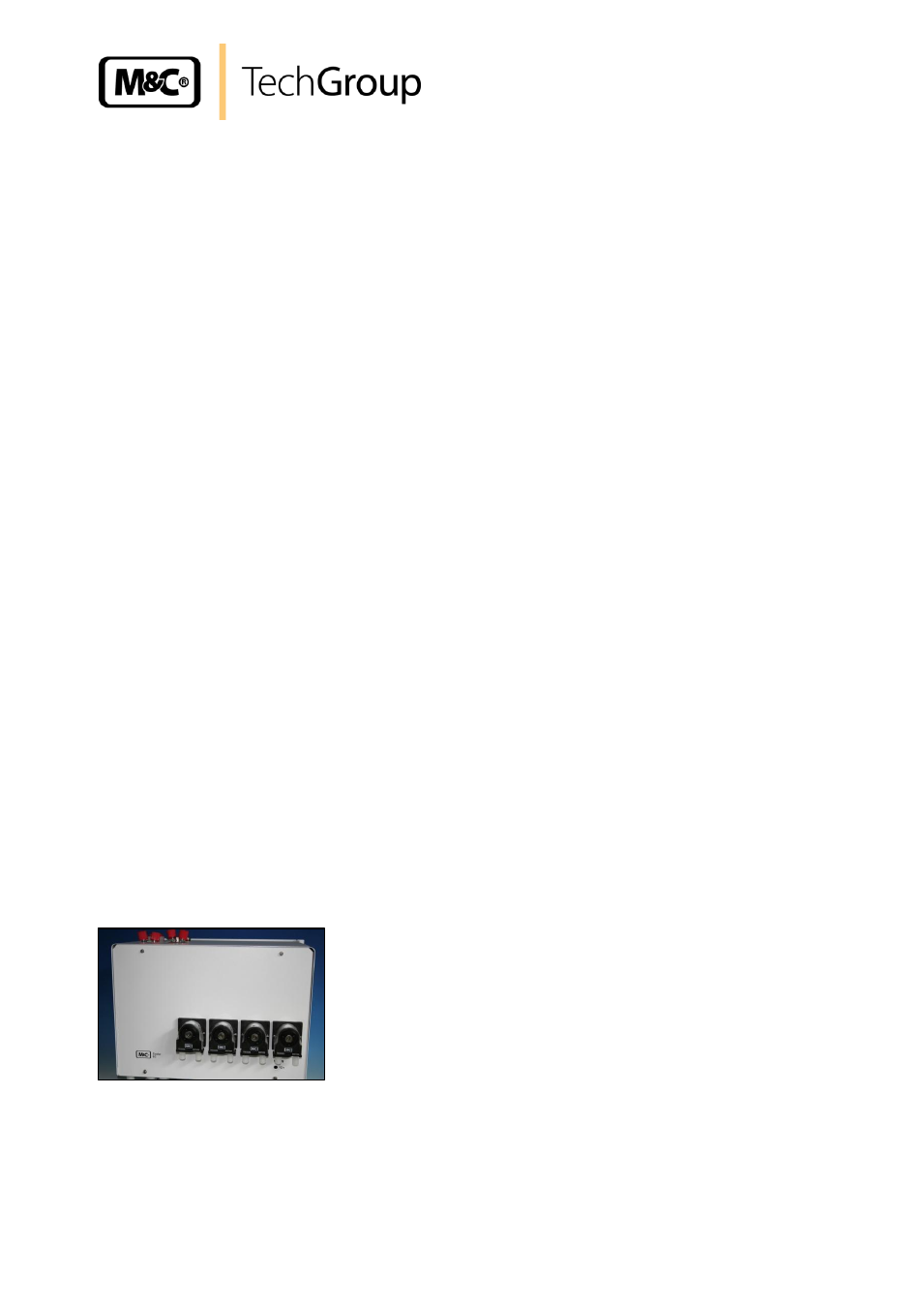
If no forced ventilation for the condenser is required, peristaltic pumps type SR25.2 can be build into
the front plate of the cooler (Part No. 01P9140).
Figure 3 Peristaltic pump SR25.2 mounted into the front panel
Instead of the unit EC-FD the universal unit EC-F optionally can be used for operation at higher
ambient temperatures up to +50°C without automatic condensate removal. The unit is mounted by
factory below the casing of the EC/ECS cooler and contains as well the above mentioned fans with
large air suction filter elements.