Introduction, Function, Figure 1 – M&C TechGroup BA-C Operator's manual User Manual
Page 7: Function diagram of ba-c air conditioning units, 6introduction, 7function
7
Gas sampling and gas conditioning technology
10-1.1.1-ME
6
INTRODUCTION
The M&C BA-C air conditioning unit has been designed especially for applications where dry, cleaned
and hydrocarbon-free air is required, independent of gas cylinders.
Typical applications are hydrocarbon measurements with flame ionisation detectors (FID) and use as
a zero gas generator for the calibration of infrared (IR) analyzers or for production of dilution gas for
M&C dilution probes.
The M&C BA-C air conditioning units are compact, operator and service-
friendly 19” plug-in units for
19”-rack mounting or wall mounting.
7
FUNCTION
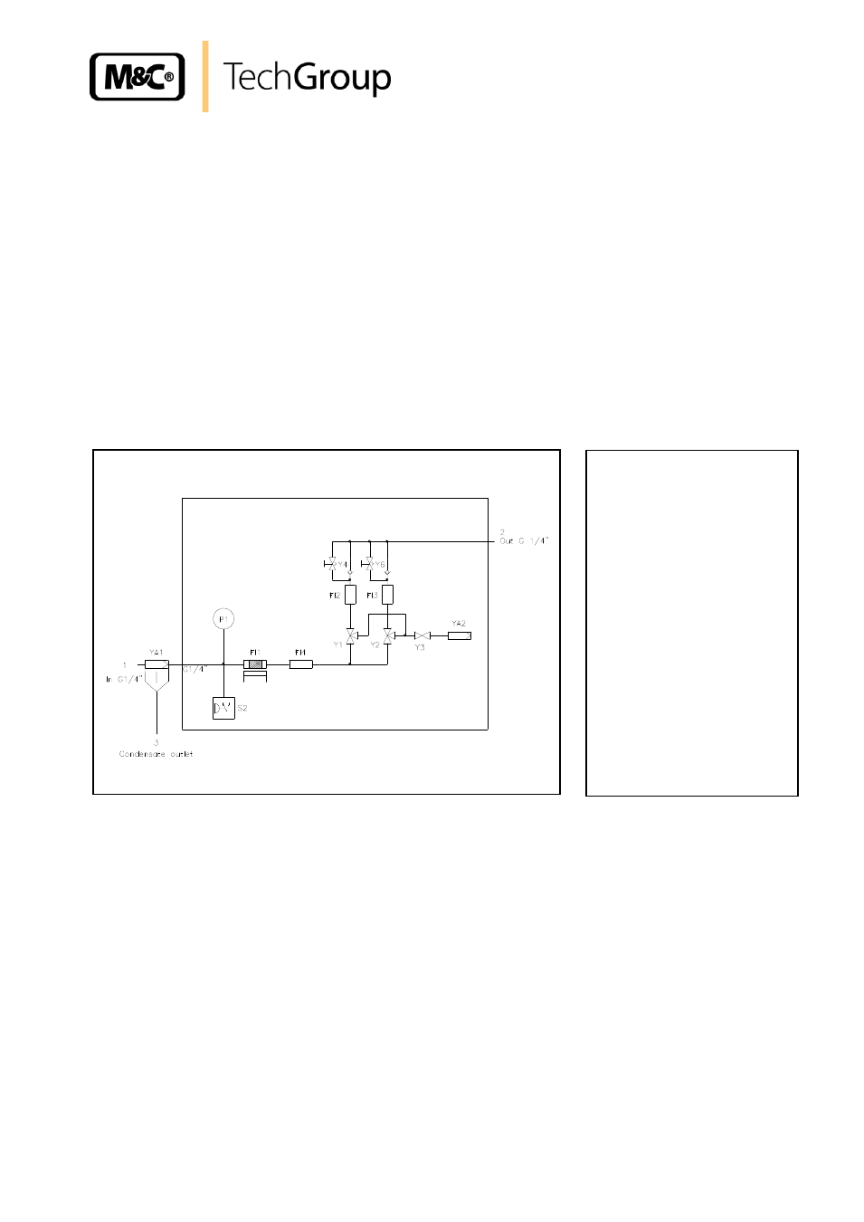
Figure 1
Function diagram of BA-C air conditioning units
The functional principle of the M&C combustion air conditioning unit is divided into two sections (see
Figure 1):
Hydrocarbon elimination section
Gas conditioning section
Hydrocarbon elimination section:
Catalytic oxidation Fl1 of hydrocarbons at a temperature of 932°F at the surface of the
platinum/palladium filling. The optimum catalyst temperature is adjusted ex works at the temperature
controller B1 of the air conditioning unit.
1 = Connection for oil-free
compressed air resp.
instrument air
2 = Outlet
3 = Condensate out
FI1 = Catalyst
FI2/3 = Adsorber
FI4 = Buffer vessel
P 1 = Manometer
S 2 = Pressure switch
Y1,2,3 = Solenoid valve
YA1 = Filter
YA2 = Pressure controller
Y4,Y6 = Needle valve