Hose connections, Electrical connections, Figure 4 – M&C TechGroup BA-C Operator's manual User Manual
Page 12
12
Gas sampling and gas conditioning technology
10-1.1.1-ME
12.2
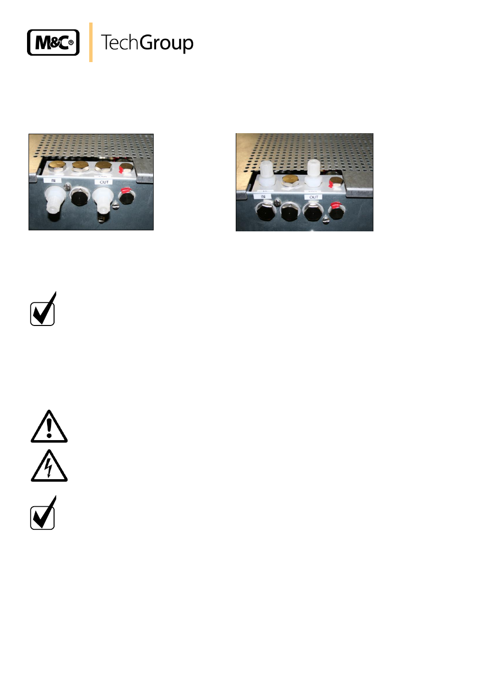
HOSE CONNECTIONS
The connection of the air in- and outlet take place on the top for wall mounting and at the back side
for 19“-rack-mounting.
19“-Mounting
Wall mounting
Figure 4
Hose connections for wall mounting or 19“-rack-mounting
For rebuilding the connections (G1/4“i) on the top or back side the blind plugs have to be displaced
correspondingly.
H I N W E I S !
Do not exchange the tube connections for inlet and outlet; the
connections are marked correspondingly.
1 = inlet; 2 = outlet
After connecting all tubings, check the closeness.
—
Appropriate connection fittings are optionally available by M&C
12.3
ELECTRICAL CONNECTIONS
W A R N I N G !
Incorrect system voltage can damage the unit. When establishing
connections, check that the system voltage corresponds with the
voltage shown on the type plate!
N O T E !
For the erection of power installations with rated voltages up to
1000V, the requirements of VDE 0100 and relevant standards and
specifications must be observed!
The main circuit is equipped with a fuse corresponding to the
nominal current (over current protection); for electrical details see
technical data.
The mains connection takes place via the fixed installed 3m mains cable:
brown = L
blue = N
green/yellow = PE
The connection of the status alarm NO takes place via the fixed installed 3m twin core cable.