Rebuilding for 19“-rack-mounting, Supply connections, Mounting and connection of the filter – M&C TechGroup BA-C Operator's manual User Manual
Page 11: Figure 3, Rebuilding the mounting brackets
11
Gas sampling and gas conditioning technology
10-1.1.1-ME
11.1
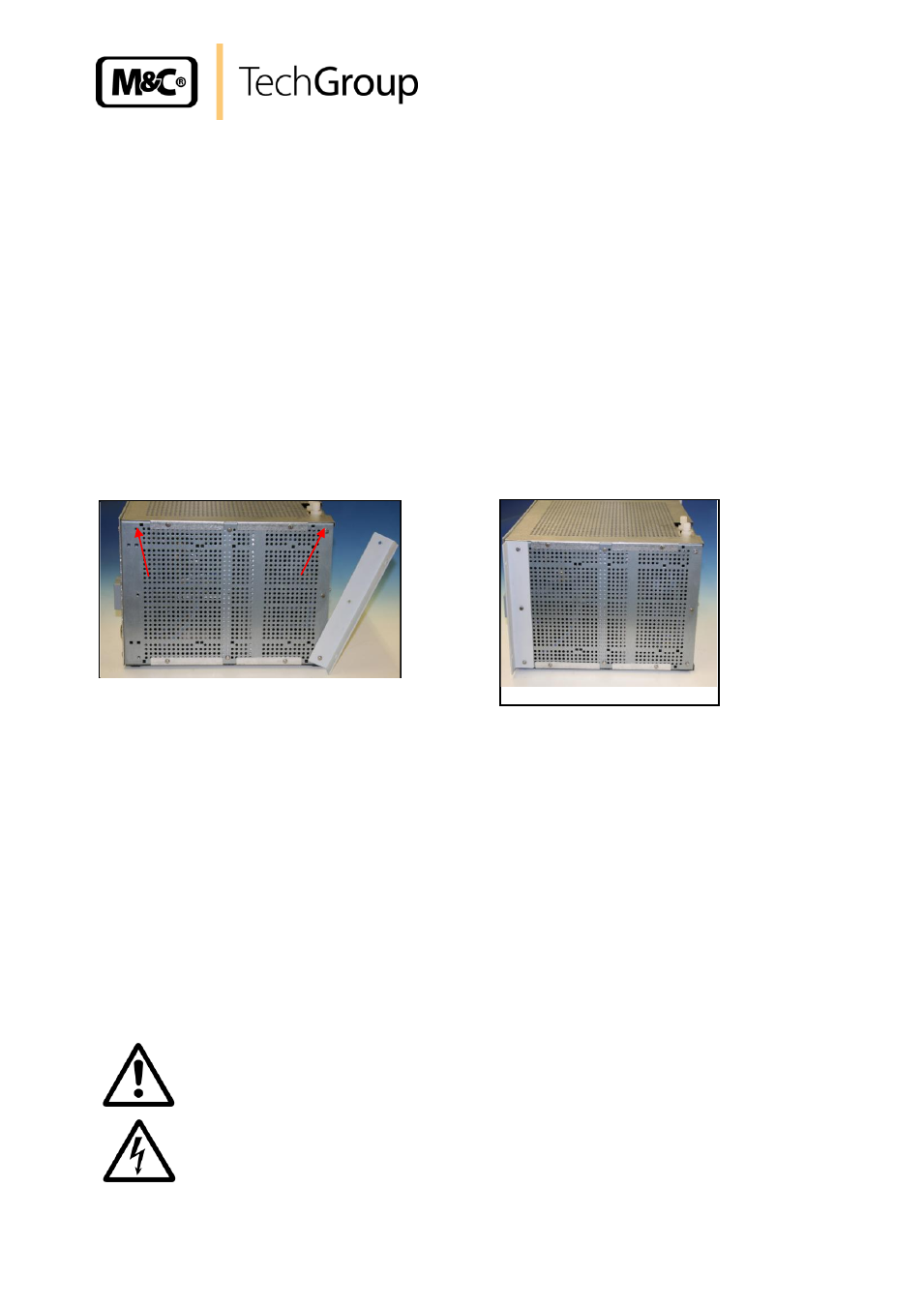
REBUILDING FOR 19“-RACK-MOUNTING
The deliverd device is prepared for wall mounting.
For 19“-rack-mounting the two mounting brackets have to be disconnected from the back side and
fixed to the front side.
For one side as a start act as follows:
Unscrew the three screws at the front of the sidewall.
Unsrew the two upper screws at the mounting bracket and only loosen the third to turn the
bracket to the back. Screw in now the two screws again.
Unscrew the lower screw from the bracket and screw it in without the bracket.
Fix the bracket at the front.
Do it the same way at the other side.
This procedure ensures that the back wall remains fixed in the device.
Figure 3
Rebuilding the mounting brackets
12
SUPPLY CONNECTIONS
12.1
MOUNTING AND CONNECTION OF THE FILTER
The separate delivered filter has to be mounted at an easy accessible place and has to be connected
with the inlet of the air conditioning unit. For the filter housing a minimum constructional size of
100mm has to be taken into consideration.
For the connection between filter an
d the inlet of the conditioning unit two connectors G ¼“-DN4/6
and 2m PTFE tube are enclosed to the delivery. The filter inlet is marked with 1 and the outlet is
marked with 2.
W A R N I N G !
The input compressed air has to be dry and oil free, because
otherwise the device will be damaged!
19“-Mounting