Introduction, 5 controller modes description – American Magnetics 286 Multi-Sensor Liquid Level Instrument (CE-Marked) User Manual
Page 21
7
Introduction
Controller Modes Description: Normal Mode
1.5 Controller Modes Description
The Model 286 provides a unique feature in the availability of three modes
for level control. The function of each mode is summarized below and a
diagram is provided to help illustrate the function. The controller modes
provide flexibility for solving a wide range of level control problems with a
minimum of external hardware or logic.
1.5.1
Normal Mode
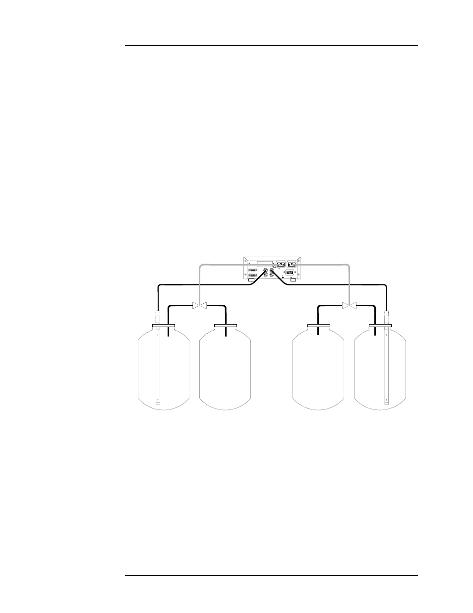
In the normal mode, as shown in Figure 1-2, Channels 1 and 2 of the
Model 286 act as independent auto-fill systems. As each level falls below
the “B” setpoint, an independent fill cycle is initiated and fills the
controlled dewar to the “A” setpoint via two separate solid-state-relay-
controlled AC outputs which can drive solenoid-actuated valves. The A and
B setpoints for Channels 1 and 2 operate as independent liquid level
control bands.
LINE: 50-60 Hz, 4.2A MAX
100-120 V
200-240 V
!
C
D
B
A
SENSOR INPUTS
COMMUNICATIONS
LINE VOLTAGE, EACH 2A MAX
1
2
J5A
J5B
(OSC REQ'D)
(OSC REQ'D)
Auto-Fill System #1
Storage Vessel #1
Controlled
Dewar #1
Auto-Fill System #2
Storage Vessel #2
Controlled
Dewar #2
Fill Valve #1
Fill Valve #2
Model 286
Figure 1-2. Normal mode diagram illustrating two
independent auto-fill systems.