Appendix – American Magnetics 286 Multi-Sensor Liquid Level Instrument (CE-Marked) User Manual
Page 110
96
Appendix
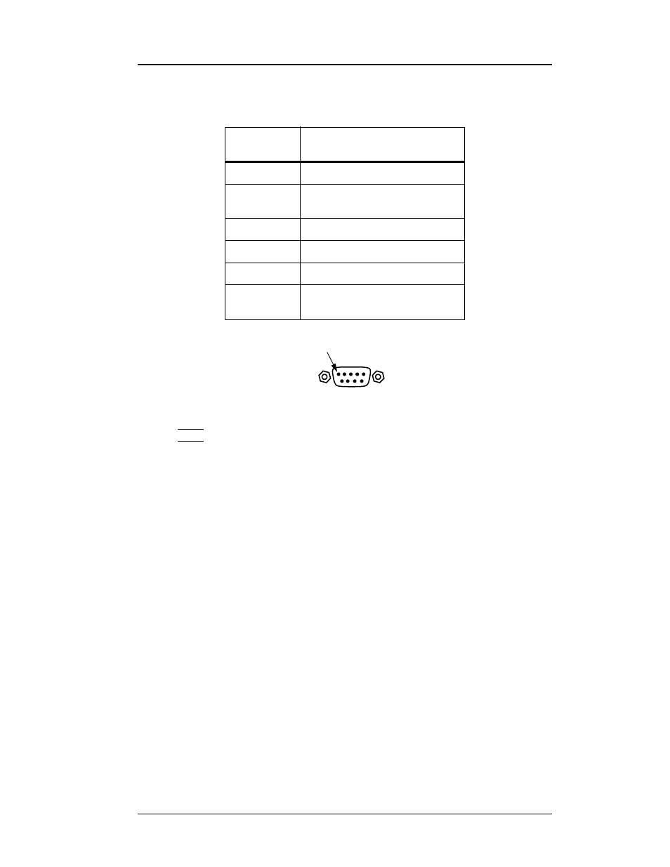
J5A and J5B connectors
A.2 J5A and J5B Connector Pinout
Note
For maximum immunity to external electrical and electromagnetic
disturbances, all external cabling (except for the AC input, controller
output, and coaxial cabling) should be shielded. The cable shield
should be connected to the chassis of the instrument by connecting to
the D-sub connector shell.
The pinouts for connectors J5A and J5B are identical. Signals within J5A
are always associated with channel 1, and signals within J5B are always
associated with channel 2, with only one exception. The exception is this —
when contact outputs are assigned to channels 3 and 4, then the relay
contacts (pins 5, 6, 7 and 8) within J5A are associated with channel 3 HI
and LO alarms (other signals with J5A remain associated with channel 1),
and the relay contacts (pins 5, 6, 7 and 8) within J5B are associated with
channel 4 HI and LO alarms (other signals within J5B remain associated
with channel 2). See paragraph 4.3.10.2 on page 53 for the ASN menu item
for assigning the HI and LO contact outputs to Channels 1 & 2 or
Channels 3 & 4.
The HI and LO alarm contacts are provided for external use by the user.
When a HI or LO alarm condition exists, the respective contact pairs are
closed. The HI and LO alarms provide 0.05% hysteresis, however the
respective contact pairs still may “chatter” if the liquid sloshes, bubbles,
etc.
J5A or J5B
Pin
Function
1 & 2
Remote contact sense (input)
3
Optional 4-20 mA current loop
output or 0-10 VDC output
4
Analog output common
5 & 6
LO alarm relay contacts (dry)
7 & 8
HI alarm relay contacts (dry)
9
Reserved for future use
(do not connect to this pin)
J5A
or B
Pin 1