Appendix – American Magnetics 286 Multi-Sensor Liquid Level Instrument (CE-Marked) User Manual
Page 109
95
Appendix
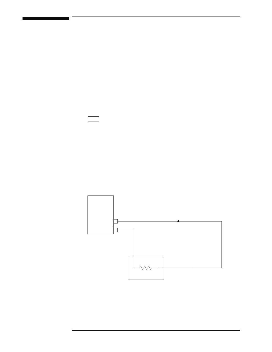
A.1 4-20 mA Current Loop Option
The 4-20 mA output utilizes pins 3 and 4 of connector J5A for Channel 1,
and pins 3 and 4 of connector J5B of connector J5B for Channel 2. These
are self-powered current loop outputs (they require no external power
supply). Refer to the figure below for wiring details. The 4-20 mA output
has a maximum compliance of 11.5 VDC. If the 4-20 mA option is installed
for a given channel, the 0-10 VDC output for that channel is not available.
Note
For maximum immunity to external electrical and electromagnetic
disturbances, all external cabling (except for the AC input, AC
outputs, and coaxial cabling) should be shielded. Each cable shield
should be connected to the chassis of the instrument by connecting to
the respective D-sub connector shell.
In the wiring diagram below, connections to the instrument indicate
connector J5A. The same connections hold true for connector J5B,
provided the current loop option was also purchased for that
channel.
Receiver
Model 286
Instrument
R
L
I
LOOP
+
_
J5A or J5B, pin 3 (
I
OUT
)
J5A or J5B, pin 4 (common)