Garmin GPS 500 User Manual
Page 29
GPS 500 Pilot’s Guide and Reference
SECTION 2
NAV PAGES
2-3
190-00181-60 Rev. G
The graphic CDI shows the current position at the center
of the indicator, relative to the desired course (the moving
course deviation needle). As with a traditional mechanical
CDI, when off course simply steer toward the needle.
The TO/FROM arrow in the center of the scale indicates
whether the aircraft is heading TO (up arrow) or FROM the
waypoint (down arrow).
Directly above the CDI appears the active leg of the
flight plan, or the direct-to destination when using the
Direct-to Key. This automatically sequences to the next
leg of the flight plan as each interim waypoint is reached.
If no flight plan or direct-to destination has been selected,
the destination field remains blank.
Quickly selecting the Default NAV Page
from any page:
Press and holding the CLR Key.
NOTE: The GPS 500 always navigates TO a
waypoint unless the OBS switch is set (preventing
automatic waypoint sequencing), or if the aircraft
has passed the last waypoint in the flight plan.
The range of the “look ahead” map display appears in
the bottom left corner. Nine scale settings, ranging from
5.0 nm to 200 nm are available. Use the RNG Key to
select the desired scale.
Adjusting the Map scale:
1) Press the up arrow on the RNG Key to zoom
out to a larger area OR,
2) Press the down arrow on the RNG Key to zoom
in to a smaller area.
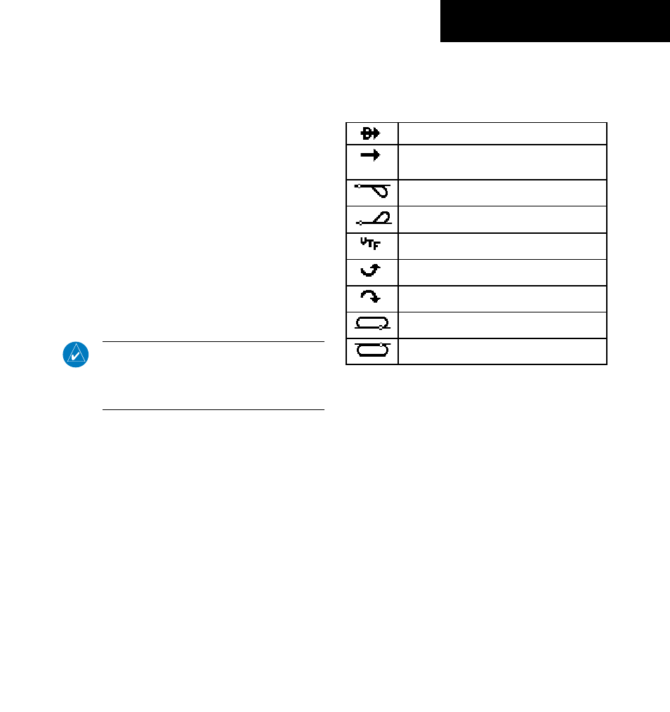
Table 2-2 shows the symbols used on the Default NAV
Page (directly above the CDI), to depict the ‘active leg’ of
a flight plan or direct to.
Direct-to a Waypoint
Course to a Waypoint, or Desired Course
between Two Waypoints
Procedure Turn
Procedure Turn
Vectors-to-Final
DME Arc to the Left
DME Arc to the Right
Left-hand Holding Pattern
Right-hand Holding Pattern
Table 2-2