Garmin GPS 500 User Manual
Page 153
GPS 500 Pilot’s Guide and Reference
8-19
SECTION 8
AUX PAGES
Selecting a menu option from the Setup
Page:
1) Press the small right knob momentarily, to
activate the flashing cursor.
2) Turn the large right knob to select the desired
menu option, and press the ENT Key (Figure
8-29).
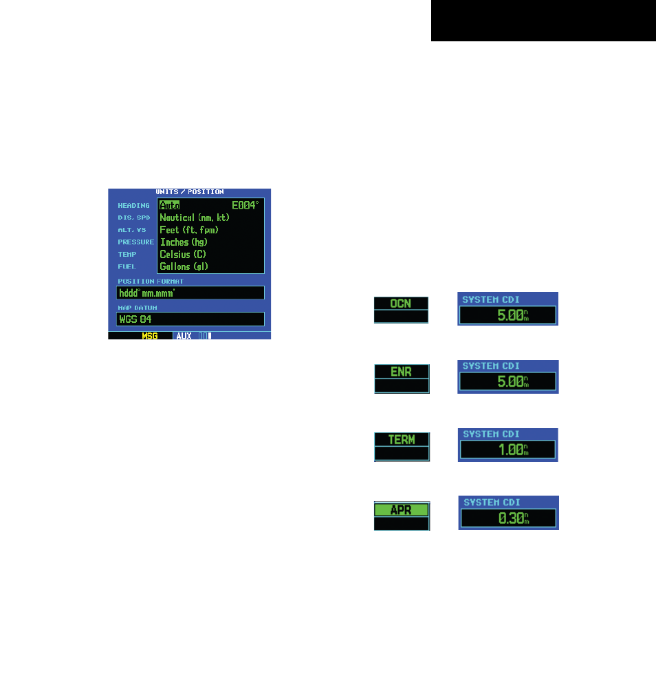
Figure 8-29 Units/Position Page
The following menu options are available:
• ‘CDI/Alarms’ - Allows the pilot to define the scale
for the GPS 500’s on-screen course deviation
indicator. The scale values represent full scale
deflection for the CDI to either side (Figure
8-30). The default setting is ‘Auto’. At this
setting, the CDI scale is set to 5 nm during the
enroute/oceanic phase of flight. Within 30 nm
of the destination airport the CDI scale gradually
ramps down to 1.0 nm (terminal area). Likewise
when leaving the departure airport the CDI scale
is set to 1.0 nm and gradually ramps UP to 5 nm
beyond 30 nm (from the departure airport).
During approach operations the CDI scale
gradually ramps down even further, to 0.3 nm.
This transition normally occurs within 2.0 nm of
the final approach fix (FAF). If a lower CDI scale
setting is selected (i.e., 1.0 nm or 0.3 nm) the
higher scale settings are not selected during any
phase of flight. For example, if 1.0 nm is selected,
the GPS 500 uses this for the enroute and
terminal phase and ramp down to 0.3 nm during
an approach. Note that the Receiver Autonomous
Integrity Monitoring (RAIM) protection limits
listed in Table 8-2 follow the selected CDI scale
and corresponding modes:
Figure 8-30 CDI Scales
CDI Scales and Corresponding Flight Phases
Oceanic
Enroute
Terminal
Approach
(for each scale/phase to be available,
‘Selected CDI’ must be set to ‘5.00nm’)
190-00181-60 Rev. G