Xerox 4213 User Manual
Page 27
INTERFACES
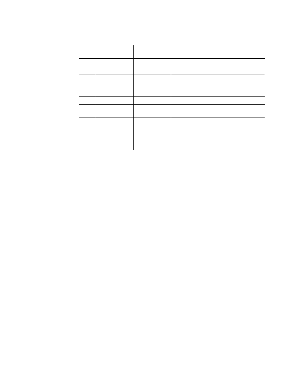
Table 1-2.
Centronics signals and pin assignments
(continued)
Pin
Direction
Signal
Description
17
Chassis ground
18
From printer
+5V (standard Centronics)
19-
29
0 volts
TWP returns All at Logic ground.
30
0 volts
INIT ground
31
To printer
INIT L
The 4213 ignores this signal.
32
From printer
ERROR L
This signal is low when the printer is in
an error state.
33
Open (standard Centronics)
34
Not used
35
Ground (standard Centronics)
36
Not used
1
These signals are the 1st and 8th bits of parallel data and are
active high for a logical 1.
XEROX 4213 LASER PRINTER PROGRAMMER REFERENCE
1-5
See also other documents in the category Xerox Printers:
- 3040 (2 pages)
- Phaser 7750 (5 pages)
- Phaser 7750 (2 pages)
- 6350 (4 pages)
- Phaser 6180 (4 pages)
- Phaser 3600 (2 pages)
- Phaser 3435 (98 pages)
- ColorQube 9202 (16 pages)
- ColorQube 9203 (13 pages)
- DocuColor 242-252-260 con Creo Spire CX260-17131 (216 pages)
- DocuColor 8000AP (4 pages)
- DocuColor 8000AP (13 pages)
- DocuPrint M760 (44 pages)
- Phaser 860 (42 pages)
- Phaser 3450 (58 pages)
- Phaser 3635MFP (10 pages)
- Phaser 5500 (5 pages)
- Phaser 6100 (7 pages)
- Phaser 7300 (28 pages)
- WorkCentre Pro 215 (62 pages)
- Color Printer Phaser 7300 (3 pages)
- Phaser Color Printer 7750 (8 pages)
- 4127 (4 pages)
- 480 (352 pages)
- 3R11474 (2 pages)
- 4500 (3 pages)
- 721P85600 (116 pages)
- 721P (2 pages)
- WorkCentre XE80 Digitaler Kopierer - Laserdrucker-9588 (58 pages)
- FreeFlow DST2-NL (23 pages)
- FaxCentre F12 (4 pages)
- 4182 (39 pages)
- Copycentre C175 (2 pages)
- ColorStix 8200 Ink Sticks 016-2045-00 (9 pages)
- DocuColor CX250 (276 pages)
- HP Toner Cartridges C9722A (2 pages)
- DocuColor 40CP (82 pages)
- 4850 (90 pages)
- Phaser 016-1300-00 (2 pages)
- X2 (41 pages)
- M123 (12 pages)
- 6130N (3 pages)
- WorkCentre PE120-120i-3133 (20 pages)
- 7300 (4 pages)
- Color Printer Phaser 6280 (158 pages)