Renesas R61509V User Manual
Page 130
R61509V
Target
Spec
Rev. 0.11 April 25, 2008, page 130 of 181
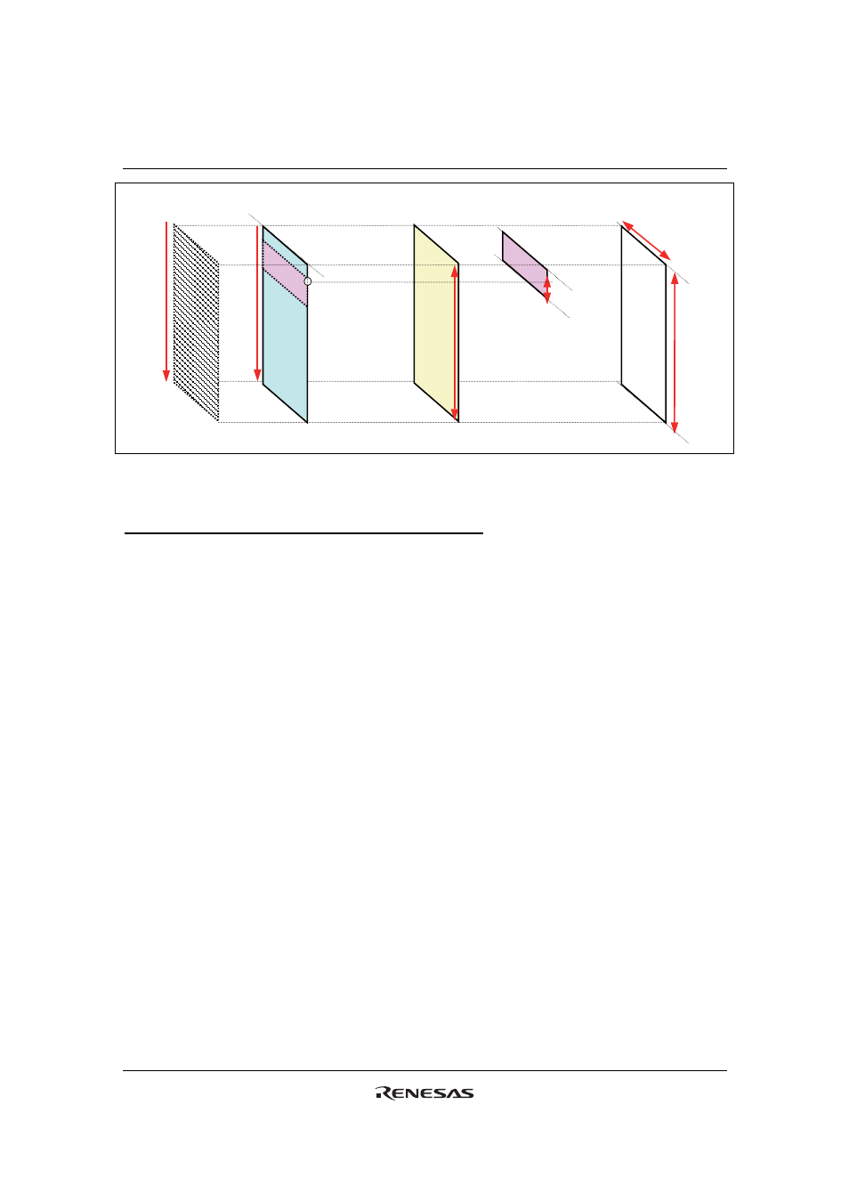
(VSA,VEA)
9’h000
9’h1AF
NL
(HSA,HEA)
Window
Address
PTDP
1
PTSA0
PTEA0
䇼LCD䇽
Panel display
position
Display data
output position
Base image
RAM address
Partial image
RAM address
RAM write
address
Partial
image
Base
image
Scan
direction
Figure 50 RAM Address, Display Position and Drive Position
Restrictions in Setting Display Control Instruction
There are restrictions in coordinates setting for display data, display position and partial display.
Screen setting
In setting the number of lines to drive the liquid crystal panel, make sure that the total number of lines is
432 lines or less (NL
≤ 432 lines).
Base image display
The base image is displayed from the first line of the screen: Base image display start position = 1
st line