Roland UA-25 User Manual
Page 10
10
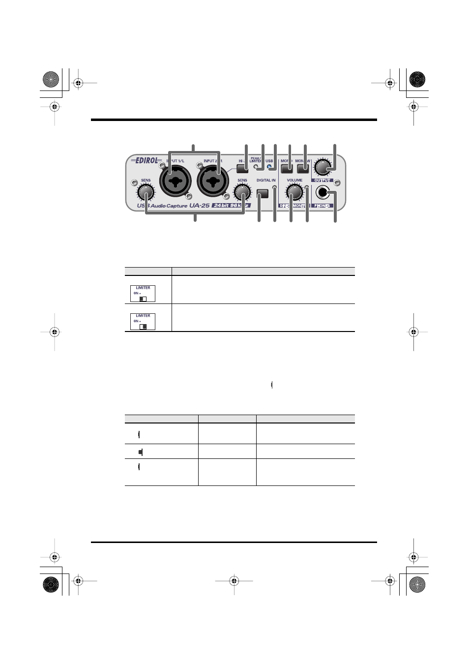
Front and rear panel
fig.front
4.
Peak/Limiter indicator
This indicates whether the input signal is distorting or the limiter is operating.
5.
USB indicator
This will light blue when the UA-25 is connected to your computer via a USB cable
and the computer has correctly detected the UA-25.
6.
Digital input switch
If you want to record the digital input, turn this on ( inward position).
This allows you to synchronize with an external digital device connected to the
digital input connector (16)
.
* When the
digital input switch
is on, you will not hear the sound from the computer.
* When the digital input switch is on, the settings of the Direct Monitor section are ignored. In
other words, operating the
direct monitor switch (8)
,
STEREO/MONO select switch (9)
,
or
direct monitor volume (10)
will have no effect.
Limiter switch
Status
Limiter on
The indicator will function as a limiter indicator. When the input signal
exceeds a certain level, the limiter will operate and the indicator will
light green.
Limiter off
The indicator will function as a peak indicator. Use the input sensitivity
knobs for each input jack to adjust the input level so that the peak indi-
cator does not light red.
Digital input switch
Mode
Status
On
Digital input mode
The input from the
digital input
connector (16)
is sent to the com-
puter.
Off
Analog input mode
The input from the
combo input
jacks (1)
is sent to the computer.
On and no digital device
is connected to the digital
input connector
LoopBack mode
The audio signal that is output from
your computer via USB will pass
through the UA-25 and return to the
computer.
1
6 7
2
8 9
10 11
4 5
12
13
3
UA-25e.book 10 ページ 2005年10月31日 月曜日 午後4時48分