Appendix a. connector wiring, Ethernet connectors, Alarm relay connector – RAD Data comm 10/100BaseT to STM-1/OC-3 Converter RIC-155 User Manual
Page 73: Appendix a connector wiring, A.1 ethernet connectors, A.2 alarm relay connector
Alarm Relay Connector
A-1
Appendix A
Connector Wiring
A.1 Ethernet Connectors
RIC-155 includes two Ethernet ports designated ETH and MNG-ETH.
lists the pinout of the Ethernet connectors.
Table A-1. ETH and MNG-ETH Connector Pinout
Pin Designation
Function
Direction
1
RX+
Receive – positive lead
Input
2
RX–
Receive – negative lead
Input
3
TX+
Transmit – positive lead
Output
6
TX–
Transmit – negative lead
Output
4, 5, 7, 8
Not connected
–
–
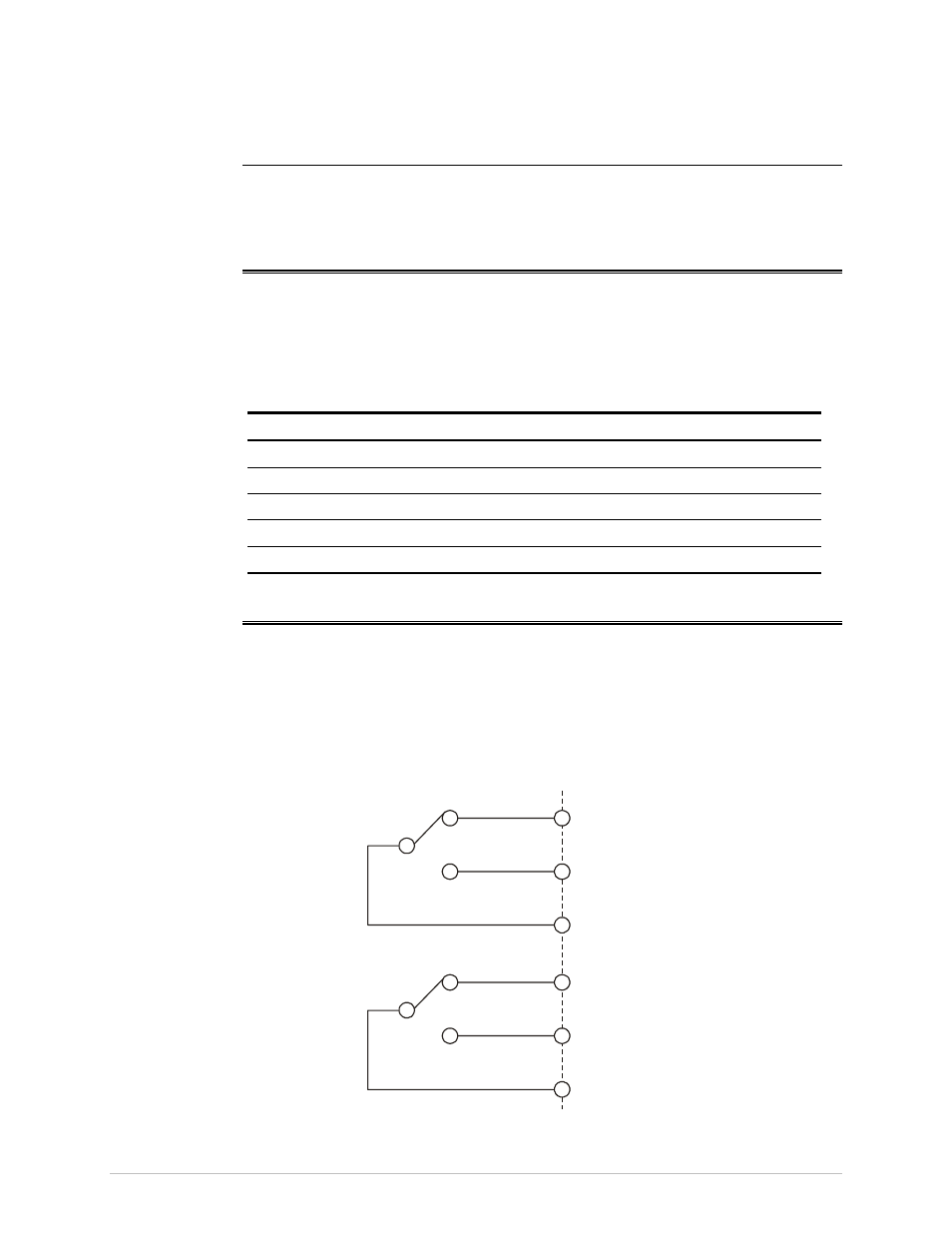
A.2 Alarm Relay Connector
The RIC-155 alarm relay terminates in a 9-pin female connector, designated
ALARM.
Figure A-1
shows the pin functions. The relay positions are shown in the
non-energized (alarm active) state.
Table A-2
lists the pinout of the ALARM
connector.
Alarm Connector
Minor-NO
1
2
6
4
5
9
Major-NO
Major Alarm Relay
Minor Alarm Relay
Minor-NC
Major-NC
Minor-COM
Major-COM
Figure A-1. ALARM Connector Wiring