Ir-ip leds, Ir-ip controls – RAD Data comm E1 Interface Converter RIC-E1 User Manual
Page 61
RIC-E1 Installation and Operation Manual
Appendix D IR-IP Interface Module
Physical Description
D-5
IR-IP LEDs
IR-IP contains LEDs, which indicate the module activity.
list the LEDs functions.
Table D-1. IR-IP LEDs Functions (Standalone RIC-E1)
LED Color
Function
INT
Green
ON – LAN is connected
ACT
Yellow
Blinks – Transmit/receive activity is detected on the Ethernet link
ERR
Red
ON – Buffer overflow occurred (during regular operation)
During power-up, provides additional indications, described below.
Table D-2. IR-IP LEDs Functions (RIC-E1/R Card)
LED Color
Function
PWR
Green
ON – RIC-E1/R is powered up
LINK
Green
ON – LAN is connected
ACT
Yellow
Blinks – Transmit/receive activity is detected on the Ethernet link
LOS
Red
ON – No E1 data is received from the link
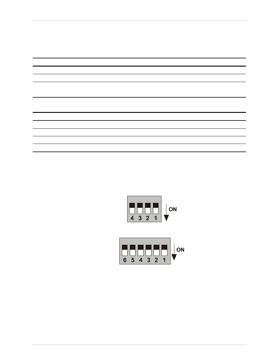
IR-IP Controls
IR-IP module contains a four-section DIP switch, as seen in
and
lists the DIP switch functions. In addition, RIC-E1/R contains
the IP LEARN pushbutton, which is similar in its functionality to the section 1 of
the IR-IP DIP switch.
Figure D-4. IR-IP DIP Switch (Standalone Unit)
Figure D-5. IR-IP DIP Switch (RIC-E1/R Card)
Order from: Cutter Networks
Ph:727-398-5252/Fax:727-397-9610
www.bestdatasource.com