Selecting the impedance, Closing the ric-e1 case, Connecting the interfaces – RAD Data comm E1 Interface Converter RIC-E1 User Manual
Page 24: Connecting the e1 line, Ained in, Connecting the, Interfaces
Chapter 2 Installation and Setup
RIC-E1 Installation and Operation Manual
2-4 Configuring
RIC-E1
Selecting the Impedance
When RIC-E1 uses the balanced interface:
• Terminate the impedance of G.703 link to 120Ω.
• Use only the RJ-45 connector to transmit full duplex data to the G.703
network over UTP or STP cable.
When RIC-E1 uses the unbalanced interface:
• Terminate the impedance of G.703 link to 75Ω.
• Use only the coaxial BNC connectors to transmit to the G.703 network via two
coaxial cables.
Closing the RIC-E1 Case
After completing the internal settings, close the unit case.
To close the RIC-E1 case:
1. Position the lower half of the RIC-E1 case on the flat surface.
2. Install the top cover making sure the top cover guides enter the corresponding
recesses at the end of the unit.
3. Secure the two screws located at the end of the unit.
4. Fit the inside tabs of the blue side panel into the unit case grooves, and slide
the side panel until snaps into place.
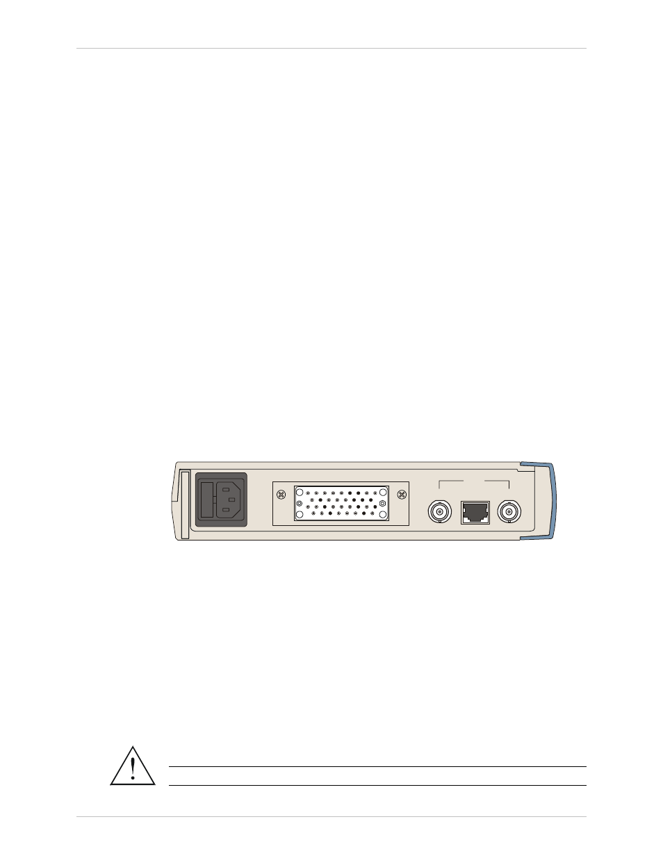
Connecting the Interfaces
and shows the rear panel of the AC-powered RIC-E1 unit.
LINK
TX
RX
V.35
Figure 2-2. RIC-E1 Rear Panel
Connecting the E1 Line
RIC-E1 link interface terminates in balanced and unbalanced connectors, marked
LINK.
To connect the balanced interface:
• Use RJ-45 male connector and connect it to the RIC-E1 RJ-45 port.
lists the balanced connector pin assignment.
To connect the unbalanced interface:
1. Connect the receive line to the back panel connector designated TX.
2. Connect the transmit line to the back panel connector designated RX.
Do not connect both balanced and unbalanced connectors.
Warning
Order from: Cutter Networks
Ph:727-398-5252/Fax:727-397-9610
www.bestdatasource.com