2 mcu setting dialog box, Important – Renesas Emulation Probe M306V8T-EPB User Manual
Page 48
M306V8T-EPB User’s Manual
3. Usage (How to Use the Emulator Debugger)
REJ10J0777-0100 Rev.1.00 2005.08.01
Page 48 of 90
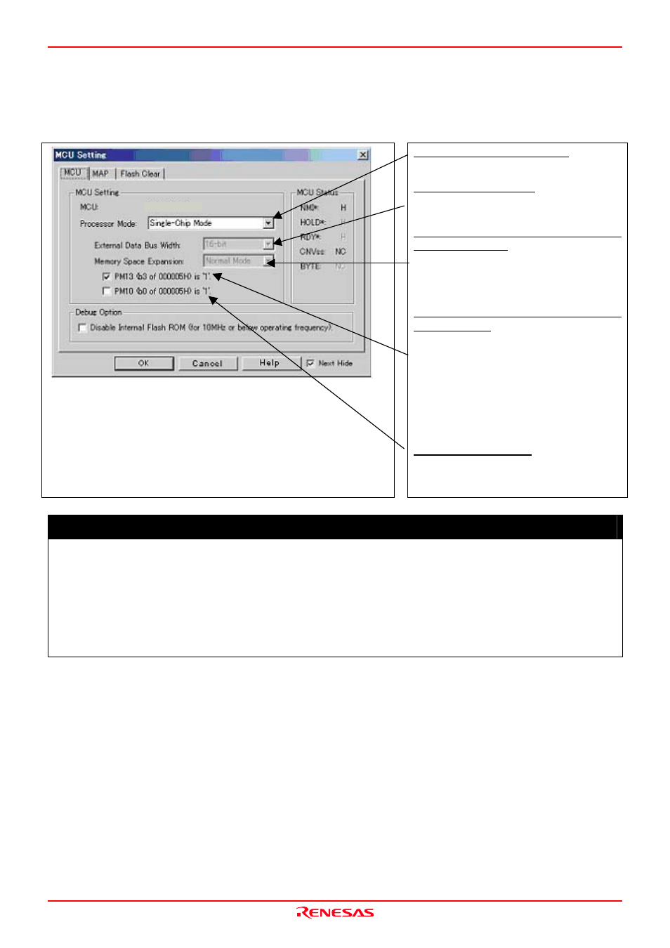
3.1.2 MCU Setting Dialog Box
MCU setting dialog box sets the information of the user system. It will be displayed after closing the Init dialog box.
(1) MCU tab
1. MCU Setting
Specifying the processor mode
Select the appropriate processor mode that suits your
system.
Specifying the bus width
When specifying memory expansion mode or
microprocessor mode, select “16-bit” for “External Data
Bus Width”.
Using or not using the memory space
expansion function
Specifies whether or not to use the memory space
expansion function when selecting memory expansion
mode or microprocessor mode. When using the memory
space expansion function, select “4MB Mode”. When
not, select “Normal Mode”
Using or not using the internal reserved
area expansion
Specifies whether or not to expand the internal reserved
area. Check this box if the internal reserved area
expansion bit (PM13) is “1”.
PM13=0:
Internal RAM area: 00400h--03FFFh
Internal ROM area: D0000h--FFFFFh
PM13=1:
Internal RAM area: 00400h--043FFh
Internal ROM area: 80000h--FFFFFh
Switching the CS2 area
Specifies CS2 area. When using the CS2 switching bit
(data block enable bit) (PM10) as “1”, check this box.
PM10 = 0: 09000h--26FFFh
PM10 = 1: 10000h--26FFFh
IMPORTANT
Notes on Selecting a Processor Mode:
When setting single-chip mode or memory expansion mode, the level of pin CNVSS of the MCU status should
be "L". The MCU status shows the pin level of the user system.
When setting microprocessor mode, the level of pin CNVSS of the MCU status should be "H".
When setting memory expansion mode or microprocessor mode, pins RDY* and HOLD* of the user system
should be "H".
When the user system is not connected, all modes are available.
M16C/6V8