Important – Renesas Emulation Probe M306V8T-EPB User Manual
Page 35
M306V8T-EPB User’s Manual
2. Setup
REJ10J0777-0100 Rev.1.00 2005.08.01
Page 35 of 90
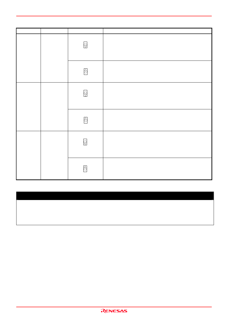
Table 2.3 Switch settings of the M306V8T-EPB (JP2, JP3, SW1 to SW5) (2/2)
Switch
Switch name
Setting Description
●T
RG
T
EPB
SW3
P
103/CA
P
(Factory-setting)
Connects pin P103/CAP of the evaluation MCU to the user system.
SW3 P103/CAP
SW3
P
103/CA
P
●T
RG
T
EPB
Connects pin P103/CAP of the evaluation MCU to the internal
circuit of the M306V8T-EPB.
●EP
B
T
RGT
SW4
CV
IN1
(Factory-setting)
Connects pin CVIN1 of the evaluation MCU to the internal circuit
of the M306V8T-EPB. When the user system is not connected, use
this setting.
SW4 CVIN1
●EP
B
T
RGT
SW4
CV
IN1
Connects pin CVIN1 of the evaluation MCU to the user system.
●EP
B
T
RGT
SW5
CV
IN2
(Factory-setting)
Connects pin CVIN2 of the evaluation MCU to the internal circuit
of the M306V8T-EPB. When the user system is not connected, use
this setting.
SW5 CVIN2
●EP
B
T
RGT
SW5
CV
IN2
Connects pin CVIN2 of the evaluation MCU to the user system.
IMPORTANT
Notes on Switch Settings:
Be sure to turn of the power before setting the switches or connecting the cables. Otherwise, the internal circuits
may be damaged.
Use the SWI and SW2 only in the combination of the setting described in Table 2.1.