Mode switch, Rs485 cable, No. 7: on) – Panasonic WJ-HD316 User Manual
Page 72
72
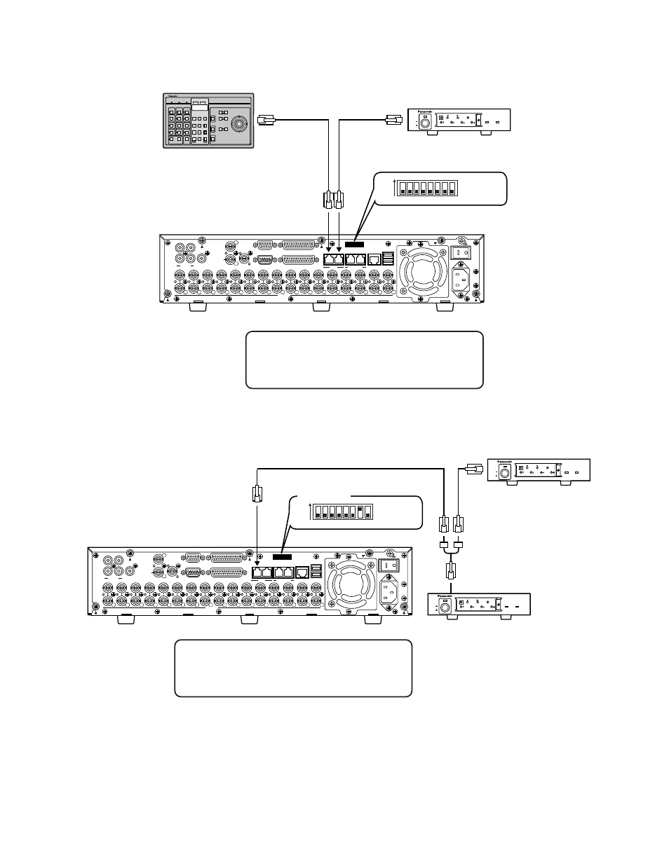
● When this unit is connected with the system device (when this unit is used as a
controller)
POWER
ON
OFF
ALARM
Data Multiplex Unit WJ-MP204
ALARM
SUSPEND
1
2
3
4
ESC
SET
RESET
SUSPEND
SET UP
ALARM
UNIT
0
9
8
7
6
5
4
3
2
1
System Controller
Controller
Termination: ON
Unit Address : 2
RS485 cable
Mode switch
(No.8 : OFF)
Coaxial communication unit
Termination: ON
Unit Address : 1
1
2
IN
OUT
CASCADE
OUT
16
16
3
15
15
14
14
13
2
1
13
12
12
11
11
10
10
9
9
8
8
7
7
6
6
5
5
4
4
3
3
2
2
1
1
VIDEO
AUDIO IN
AUDIO OUT
MONITOR OUT CASCADE IN
MONITOR (VGA)
ALARM/CONTOROL
SERIAL
ALARM
POWER
COPY 1
MODE
EXT STORAGE
10/100BASE-T
RS485(CAMERA)
DATA
AC IN
SIGNAL GND
1
4
2
6 7 8
1 2 3 4 5
ON
"PS·Data setup" of "Comm" on the SETUP MENU
• Unit Address (System)
: 1
• Unit Address (Controller) : 2
POWER
ON
OFF
ALARM
Data Multiplex Unit WJ-MP204
ALARM
SUSPEND
1
2
3
4
ESC
SET
RESET
SUSPEND
SET UP
ALARM
UNIT
0
9
8
7
6
5
4
3
2
1
POWER
ON
OFF
ALARM
Data Multiplex Unit WJ-MP204
ALARM
SUSPEND
1
2
3
4
ESC
SET
RESET
SUSPEND
SET UP
ALARM
UNIT
0
9
8
7
6
5
4
3
2
1
RS485 cable
Mode switch
(No. 7: ON)
1
2
IN
OUT
CASCADE
OUT
16
16
3
15
15
14
14
13
2
1
13
12
12
11
11
10
10
9
9
8
8
7
7
6
6
5
5
4
4
3
3
2
2
1
1
VIDEO
AUDIO IN
AUDIO OUT
MONITOR OUT CASCADE IN
MONITOR (VGA)
ALARM/CONTOROL
SERIAL
ALARM
POWER
COPY 1
MODE
EXT STORAGE
10/100BASE-T
RS485(CAMERA)
DATA
AC IN
SIGNAL GND
1
4
2
6 7 8
1 2 3 4 5
ON
Coaxial communication unit
Termination: ON
Unit Address : 3
Coaxial communication unit
Termination: OFF
Unit Address : 2
"PS·Data setup" of "Comm" on the SETUP MENU
• Unit Address (System)
: 1
• Unit Address (Controller) : 1