Rj45 – Perle Systems Perle IOLAN DS1 User Manual
Page 189
Pinouts and Cabling Diagrams 189
Serial Pinouts
The power in pin, pin 12, can be 9-30V DC.
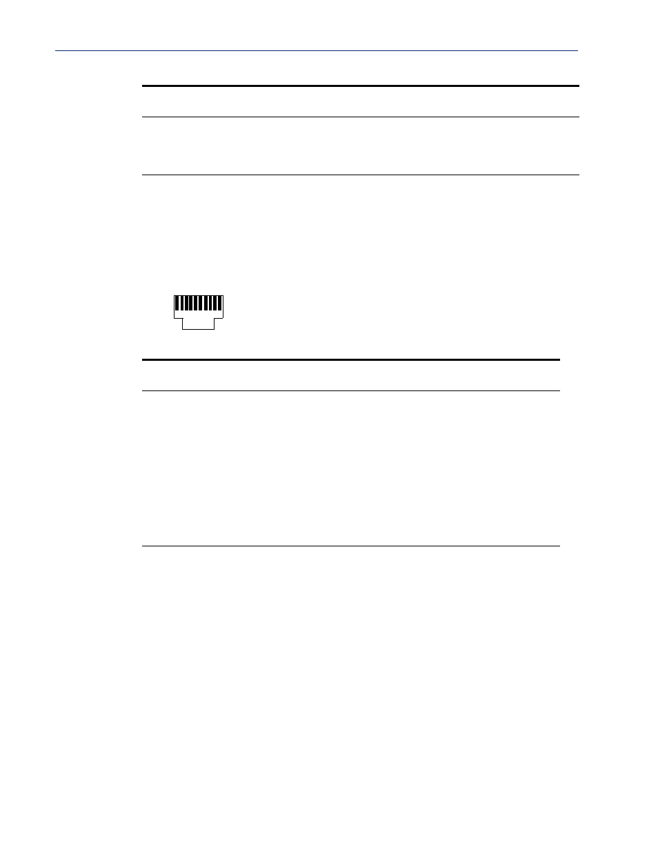
RJ45
This section defines the pinouts for the RJ45 connection used on the DS and TS IOLAN. The TS
IOLAN does not support power in, so use the 8-pin mappings for this model. These pinouts do not
apply to I/O models.
The following table provides pinout information:
The power in pin, Pin 1, can be 9-30V DC. The 2-port IOLAN has power in on Port 2 only.
21
TxD+
TxD+
DATA+
22
TxD-
TxD-
DATA-
25
RTS+
Pinout
10-pin
Pinout
8-pin
EIA-232
EIA-422
EIA-485
Full Duplex
EIA-485
Half Duplex
1
Power In
Power In
Power In
Power In
2 (in)
1
DCD
3 (out)
2
RTS
TxD+
TxD+
DATA+
4 (in)
3
DSR
5 (out)
4
TxD
TxD-
TxD-
DATA-
6 (in)
5
RxD
RxD+
RxD+
7
6
GND
GND
GND
GND
8 (in)
7
CTS
RxD-
RxD-
Pinout
EIA-232
EIA-422
EIA-485
Full Duplex
EIA-485
Half Duplex
Pin 10
Pin 1