Theory of operation, Power board, E-8 power wave 450 – Lincoln Electric INVERTEC POWER WAVE 450 SVM112-B User Manual
Page 56
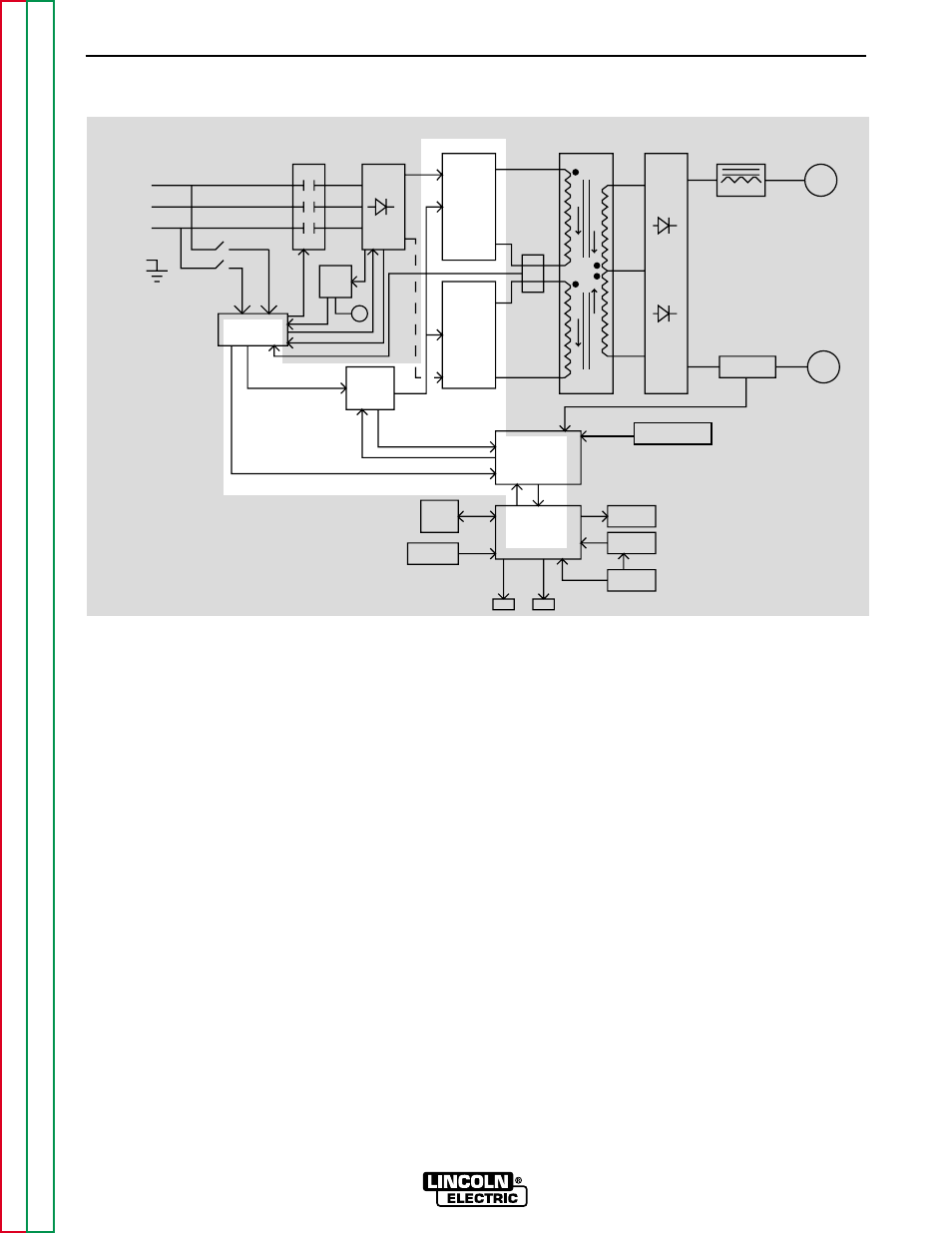
THEORY OF OPERATION
E-8
E-8
POWER WAVE 450
POWER BOARD
The Power Board provides gate drives for the FETs on
the Switch Boards. It does so based on the “turn-on”
signals it receives from the Control Board. One func-
tion of the Power Board is to isolate the Control Board
from the Switch Boards. The Power Board also pro-
vides the other printed circuit boards with the DC volt-
age supply they require.
FIGURE E.8 – POWER BOARD
NOTE: Unshaded areas of Block Logic Diagram are the subject of discussion.
CONTROL
BOARD
DISPLAY
BOARD
PROTECTION
BOARD
AUX.
TRANS
POWER
BOARD
CT
CONTACTOR
INPUT
INPUT
RECTIFIER
AND
RECONNECT
SWITCH
BOARD
FET
ASSEMBLY
SWITCH
BOARD
FET
ASSEMBLY
MAIN
TRAMSFORMER
OUTPUT
RECTIFIER
SHUNT
CHOKE
POSITIVE
NEGATIVE
SNUBBER
AND
LEADS
SENSE
LCD
DISPLAY
KEYPAD
OVERLAY
WATER
COOLER
PC
INTERFACE
INPUT
LINE
SWITCH
FAN
WF1
WF2
THREE
PHASE
INPUT
POWER
LEFT
RIGHT
- Invertec V310-T DC (2 pages)
- VANTAGE 500 (CE) 11575 (50 pages)
- INVERTEC V350-PRO SVM152-A (155 pages)
- IMVERTEC V160-T (36 pages)
- IDEALARC CV-300 (112 pages)
- AUTO-DARKENING HELMET IM10001 (12 pages)
- IM10111 IDEALARC R3R-500-I (28 pages)
- IM10110 IDEALARC R3R-400 (25 pages)
- IM10051 INVERTEC V311-T AC_DC (38 pages)
- IM10059 SQUARE WAVE TIG 175 (30 pages)
- IM10096 POWER MIG 256 (37 pages)
- IM10096 POWER MIG 256 (38 pages)
- IM10105 POWER MIG 350MP (47 pages)
- IM10115 FLEXTEC 650 (42 pages)
- IM10132 FLEXTEC 650 (56 pages)
- IM10132 FLEXTEC 650 (36 pages)
- IM10018 IDEALARC DC-600 VRD (55 pages)
- IM10107 IDEALARC DC-400 (40 pages)
- IM10062 FLEXTEC 450 (72 pages)
- IM10091 FLEXTEC 450 CE (40 pages)
- IM10094 RED-D-ARC FX450 (31 pages)
- IM10157 12_24V 10A Auto HF Household Charger (16 pages)
- IM10139 JUMP STARTER (12 pages)
- IM10149 POWER WAVE ADVANCED MODULE (46 pages)
- IM10102 AIR VANTAGE 650 (60 pages)
- IM10103 AIR VANTAGE 700 (AU) (57 pages)
- IM10065 AIR VANTAGE 500 CUMMINS (54 pages)
- IM10066 AIR VANTAGE 500 (AU) (56 pages)
- IM10041 VANTAGE 500 CUMMINS (56 pages)
- IM10128 AIR VANTAGE 500 KUBOTA (AU) (56 pages)
- IM10090 ARC TRACKER (48 pages)
- IM10147 AUTO-DARKENING HELMET (12 pages)
- IM10087 AutoDrive 19 CONTROLLER (28 pages)
- IM10125 AutoDrive 19 TANDEM (34 pages)
- IM10069 AutoDrive 4R100 (32 pages)
- IM10145 AUTOPRO 20 (24 pages)
- IM10025 BIG RED 500 (40 pages)
- IM10019 BIG RED 600 (41 pages)
- IM10005 BULLDOG 140 (46 pages)
- IM10074 BULLDOG 5500 (56 pages)
- IM10067 CENTURY AC120 (20 pages)
- IM10109 CIRCULATOR (36 pages)
- IM10109 CIRCULATOR (33 pages)
- IM10153 CLASSIC 300 HE (60 pages)