Theory of operation, Control board, E-7 power wave 450 – Lincoln Electric INVERTEC POWER WAVE 450 SVM112-B User Manual
Page 55
THEORY OF OPERATION
E-7
E-7
POWER WAVE 450
CONTROL BOARD
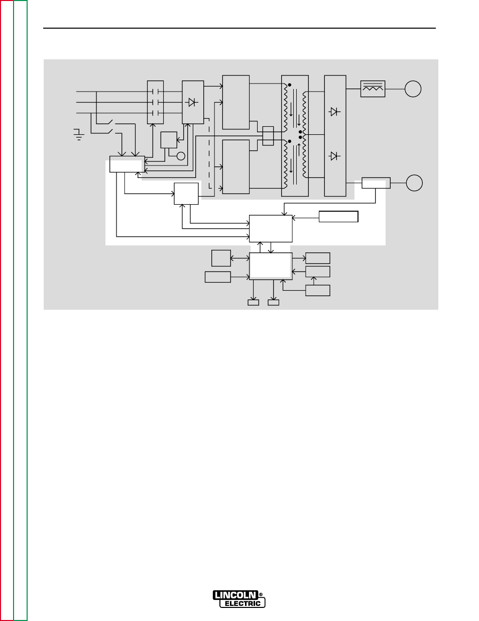
The Control Board is at the heart of controlling the out-
put of the machine. With the information it receives
from the Shunt (current feedback), the voltage sensing
leads, the wire feeder(s), and the other printed circuit
boards, the Control Board optimizes the welding
results by regulating the FETs’ switching times, which
in turn control the output of the machine. The Control
Board also monitors the thermal protection devices
and the regulation and fault signals produced on the
Protection Board.
FIGURE E.7 – CONTROL BOARD
NOTE: Unshaded areas of Block Logic Diagram are the subject of discussion.
CONTROL
BOARD
DISPLAY
BOARD
PROTECTION
BOARD
AUX.
TRANS
POWER
BOARD
CT
CONTACTOR
INPUT
INPUT
RECTIFIER
AND
RECONNECT
SWITCH
BOARD
FET
ASSEMBLY
SWITCH
BOARD
FET
ASSEMBLY
MAIN
TRAMSFORMER
OUTPUT
RECTIFIER
SHUNT
CHOKE
POSITIVE
NEGATIVE
SNUBBER
AND
LEADS
SENSE
LCD
DISPLAY
KEYPAD
OVERLAY
WATER
COOLER
PC
INTERFACE
INPUT
LINE
SWITCH
FAN
WF1
WF2
THREE
PHASE
INPUT
POWER
LEFT
RIGHT