Amplifier shunt, Electrical diagrams, G-19 – Lincoln Electric INVERTEC POWER WAVE 450 SVM112-B User Manual
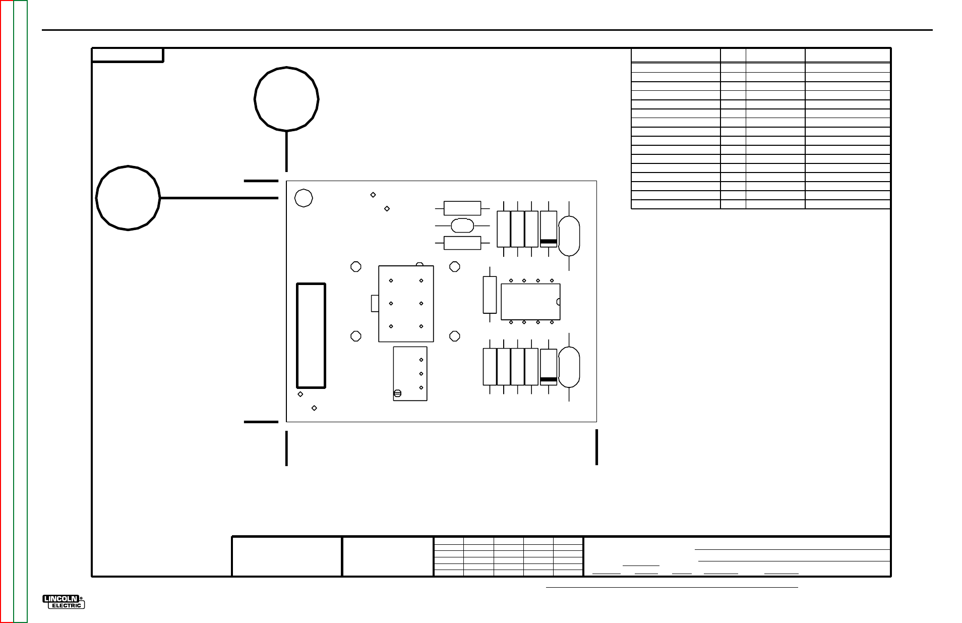
Page 287: Pc board assembly- shunt
NOTE:
Lincoln Electric assumes no responsibility for liablilities resulting from board level troubleshooting. PC Board repairs will invalidate your factory warranty. Individual Printed Circuit Board Components are not available from Lincoln Electric. This information is pro-
vided for reference only. Lincoln Electric discourages board level troubleshooting and repair since it may compromise the quality of the design and may result in danger to the Machine Operator or Technician. Improper PC board repairs could result in damage to the
machine.
ELECTRICAL DIAGRAMS
G-19
POWER WAVE 450
PC BOARD ASSEMBLY- SHUNT
I T E M
R E Q ’ D
PA R T N O
D E S C R I P T I O N
CAPACITORS = MFD/VOLTS
17150-2
Ch’ge. Sht. No.
11-21-97G
4-20-2000D
INVERTER WELDERS
SHUNT AMPLIFIER P.C. BD. ASSEMBLY
LJB
FULL
17150-2
J.J.
11-4-97
M17150-1
THE LINCOLN ELECTRIC CO.
CLEVELAND, OHIO U.S.A.
EQUIP.
TYPE
SCALE
SUBJECT
DR
DATE
CHK
REF.
SUP’S’D’G
SHT.
NO.
M
M
C1
1 S16668-5
.022/50
C2,C3
2 S16668-11 .1/50
DZ1,DZ2
2 T12702-29
1N4744A
R1,R3
2 S19400-5110 511 1/4W
R2,R4
2 S19400-4751 4.75K
R6
1 S19400-5620
562 1/4W
R7
1 S16296-3
500 1/2W TRIMMER
J50
1 S18248-6
HEADER
R5,R8
2 S19400-3923 392K 1/4W
R9
1 S19400-1301 1.3K 1/4W
R10,R11
2 S19400-1000
100 1/4W
X1
1 S15128-13
PRECISION OP AMP IC
AMPLIFIER
SHUNT
R9
R11
R10
R6
R5
R8
R2
R4
R3
R1
C3
C2
C1
DZ2
DZ1
X1
J50
R7
M17150-2
0
1.63
0
1.75
+.04
-
2.25
+.04
-
.13
G-19