Troubleshooting & repair, Warning – Lincoln Electric INVERTEC POWER WAVE 450 SVM112-B User Manual
Page 204
F-144
F-144
QUICK VOLTAGE CALIBRATION
(continued)
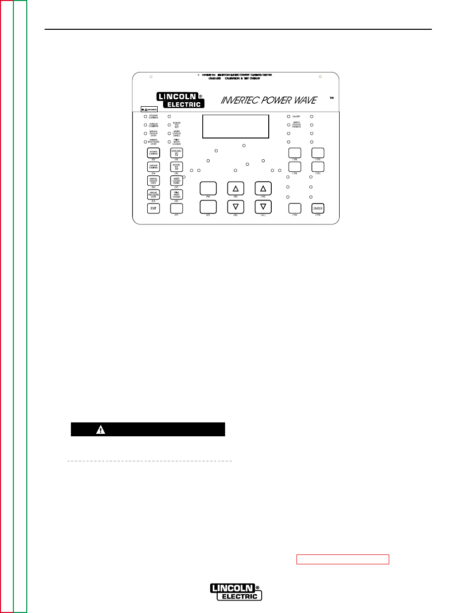
FIGURE F.54 - TEST AND CALIBRATION OVERLAY
TROUBLESHOOTING & REPAIR
PROCEDURE
1. Before changing or disturbing the display
board, power up the machine with the
L9660-255 Test and Calibration overlay in
place. See Figure F.54.
2. Press the Voltage Calibration function (32).
The machine should display the following:
VOLTAGE WIRE
+ POLARITY (+67A)
3. Press the Enter Key (133) on the lower right
side of the overlay. The machine should
display the following:
ADJUST TO 30V
CALIBRATION #=XX
NOTE: Here “XX” indicates a particular cali-
bration number for a given voltage sensing
point.
The machine’s output terminals will be electri-
cally “HOT” when the Enter Key is pressed.
4. Record the number displayed for the +67
wire and press the Enter Key (133) again.
5. Repeat the process by pressing the Voltage
Calibration function again. The next sens-
ing lead may be selected by pressing the
down Arrow Key (101). The above proce-
dure must be repeated six times to obtain
and record the calibration number for six
different voltage sensing points. These
points are the following:
+ Polarity (+67A)
+ Polarity (+67B)
- Polarity (+21A)
- Polarity (+21B)
+ Polarity
- Polarity
6.
Install the “new” replacement display
board.
7. With the L9660-255 overlay installed, apply
power to the machine. Press the Voltage
Calibration function (32). Enter the re-
corded calibration numbers for each of the
six voltage sensing points. The calibration
numbers are entered by selecting the prop-
er sensing point (lead), pressing the Enter
Key (133) and obtaining the display that
reads:
ADJUST TO 30V
CALIBRATION #=XX
The calibration number is changed using the
up/down Arrow Keys (100, 101). Press the
Enter Key when the desired number is dis-
played.
8. Repeat the process for all six sensing
points (leads).
9. Perform the Sensor Calibration Test.
POWER WAVE 450
WARNING