Appendix g: cabling schematic, 3000i installation guide, Fa n – Smart Technologies 3000i User Manual
Page 59
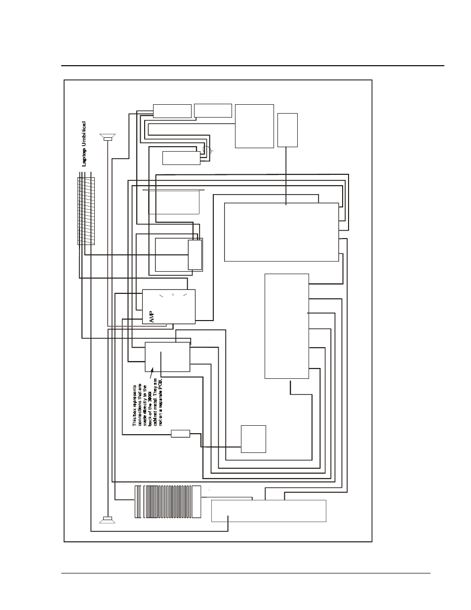
3000i Installation Guide
51
Appendix G: Cabling Schematic
Mai
n I
n
La
pt
op
Au
x
Pr
oj
e
ct
o
r
PC
12
v P
ow
er
Proj
ec
to
r
Pw
r
Vi
de
o
Out
Se
ri
a
l
Vi
de
o
1
In
V
ideo
2
In
Co
m
p
Vid
eo
PC
SC7
Control Panel
PC
Au
di
o
Wi
re
le
ss
K
e
yboa
rd
S-
Vid
e
o
Se
ri
a
l
V
ide
o 1
Ne
t
P
w
r
P
rint
er
12
V
60
-016
Pr
in
te
r
Vi
de
o
Ou
t
Co
m
p
Vi
de
o
IN
Ne
t
In
Fa
n
C
o
nt
ro
ller
Boa
rd
PC
1
in
PC2 in
RCA in
RCA out
DC
I2
C
Le
ft
C
han
ne
l
Ri
gh
t
C
h
an
ne
l
V
ideo 2
IN
S
-V
ideo
IN
Fa
n
PT10
RB
2-
67
T
hes
e 3
c
a
bl
es
ar
e
bu
ndl
ed t
og
et
her
.
La
yo
u
t i
s
ro
ug
hl
y th
e s
a
me
as
vi
ew
ed
fr
o
m
fr
o
nt
of
cab
in
et
lo
o
ki
n
g i
n
si
d
e t
o Co
nn
ec
tio
n P
a
ne
l
W
ir
e
le
ss
K
e
yb
oar
d
IR R
e
ce
iv
er
Po
w
er
Ba
r
To
S
B
X
-P
o
rt
20/300
0i
PC
2
in PC
1
in
I2
C
I2
C
I2
C
Th
ese
three
co
nnect
ors
go d
ire
ctly
fro
m the
Au
dio
Am
p boa
rd t
o th
e ba
ck o
f
th
e C
onnec
tion
Pane
l
Metal Panel - may
be replaced with a
Room Control
Module