System controller – Sanyo CHX03652 User Manual
Page 89
3-45
1
2
3
4
5
6
7
8
Control of Mini ECO-i SYSTEM
4. System Controller
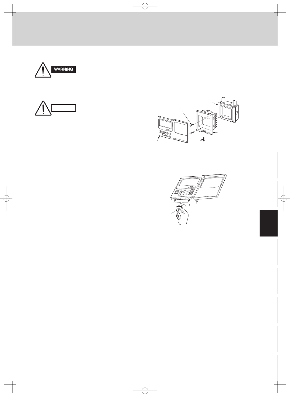
■ How to install the system controller
Fig. 3-25
2041_C_I
System
controller
Switch box
(no cover)
M4
× 30 or 5/32” × 1-3/16”
Screws (2)
Flat-top
Screw
Back case
Gap
Coin
2042_M_I
Gap
Fig. 3-26
Do not supply power to the
unit or try to operate it until
the tubing and wiring to the
outdoor unit is completed.
9-1. System Controller Installation
● Do not twist the control
wiring with the power
wiring or run it in the
same metal conduit,
because this may cause
malfunction.
● Install the system con-
troller away from sources
of electrical noise.
● Install a noise filter or
take other appropriate
action if electrical noise
affects the power supply
circuit of the unit.
● If local codes allow, this system controller can be
mounted using a conventional wall box for flush
mounting.
(1)
Remove the flat-top screw on the bottom of the
back case. When you open up the decorative
cover, you will see two gaps under the system
controller. Insert a coin into these gaps and
remove the back case. (Figs. 3-25, 3-26)
(2)
Connect the wires to terminal base of the system
controller (see next page).
(3)
Attach the back case with the 2
×
M4 or 5/32” screws
provided.
(4)
To finish, fit the back tabs of the back case into
the system controller and mount it using the flat-
top screw.
CAUTION