4-way air discharge semi-concealed type (x type), Mini eco-i system unit specifi cations – Sanyo CHX03652 User Manual
Page 131
4-21
Mini ECO-i SYSTEM Unit Specifi cations
1
2
3
4
5
6
7
8
5
3
4
9
7
2
2
2
1
2
8
10
8
7
6
6-19/64
12-9/16
3-13/16
3-13/16
18-57/64
18-57/64
1-3/8 less than
1-3/8 less than
(15-3/4)
2-23/64
9-27/32
2-3/4
7-13/32
2-15/16
1-3/16
19/32
1-3/16
6-19/64
3-5/32
6-19/64
8-17/64
13-21/32
1-49/64
4-29/64
20-15/64
20-15/64
3-15/32
3-15/32
15-3/64
1-3/8
37-13/32
37-13/32
X
7-13/64
33-55/64 ~ 35-53/64
28-15/32
33-5/64
7-13/64
33-55/64
~
35-53/64
31-7/64
33-5/64
*
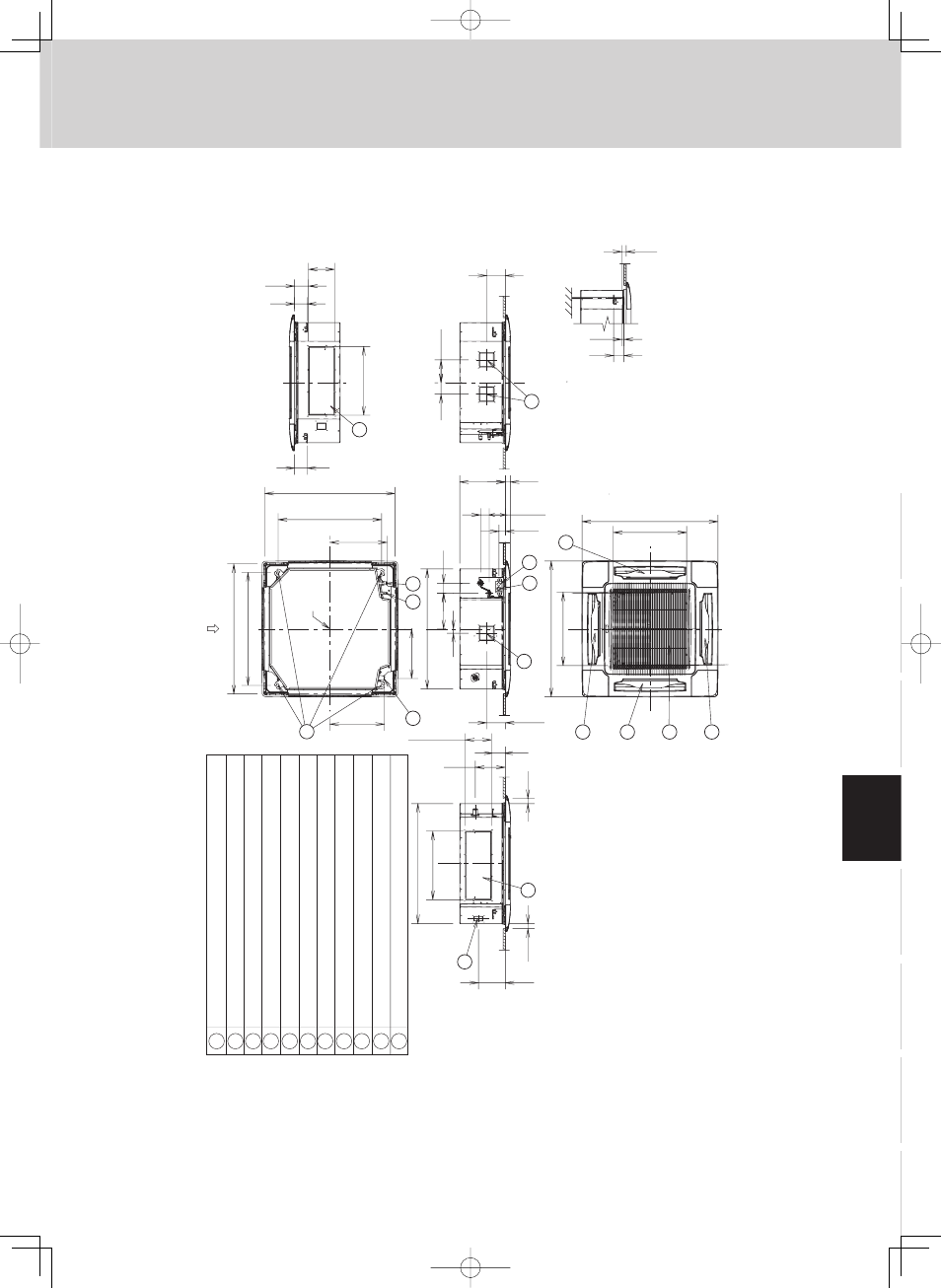
The length of the suspension
bolts should be selected so that
there is a gap of 1-3/16" or
more belo
w the lo
w
er surf
ace of
the ceiling (19/32" or more
belo
w the lo
w
er surf
ace of the
main unit), as sho
wn in the
figure at r
ight.
If the suspension
bolt is too long, it will contact
the ceiling panel and the unit
cannot be installed.
Ceiling opening
dimensions
Ceiling opening dimensions
Suspension bolt pitch
X vie
w
Suspension bolt pitch
Center
of panel
Air intak
e
Discharge outlet
Refr
iger
ant tubing (liquid tube) ш3/8" (ш9.52) (flared)
Refr
iger
ant tubing (gas tube) ш5/8" (ш15.88) (flared)
Dr
ain tube connection por
t
VP25 (outer dia.
ø1-1/4")
P
o
w
er supply por
t
Discharge duct connection por
t (ø5-29/32")
V
apor
izing-type humidifier (optional) installation point
Suspension bolt hole (4-15/32"
×
1-29/64" hole)
F
resh air intak
e duct connection por
t (ø3-15/16")
Inter-unit control wir
ing
1
2
3
4
5
6
7
8
9
10
11
11
2. 4-Way Air Discharge Semi-concealed Type (X Type)
Indoor unit: 36 type