Outdoor unit – Sanyo CHX03652 User Manual
Page 116
4-6
1
2
3
4
5
6
7
8
Mini ECO-i SYSTEM Unit Specifi cations
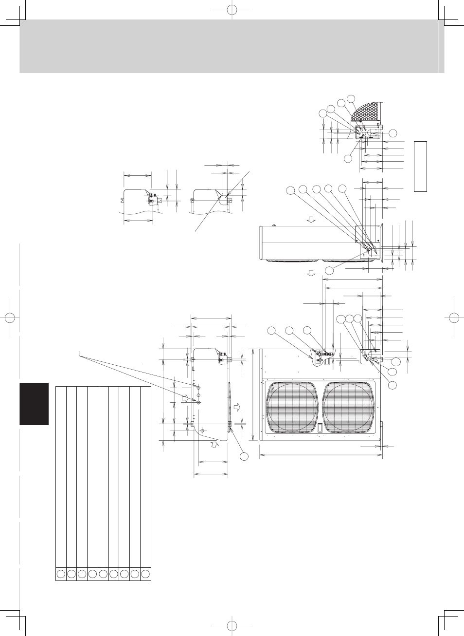
1. Outdoor Unit
1-3. Dimensional Data
CHX03652
CHX06052
6-11/16
13-3/8
11-21/32
25/32
13/32
14-31/32
15-15/16
13/32
19/32
25-31/32
37
Wind
direction
8
-5/
8
5-29/32
1/2
1/2
1/2
1/2
2-
3/4
4-5/16
1
2
3
4
5
6
7
8
9
2-7/32
4-19/32
11-11/32
10-25/32
5/16
2-3/8
2-7/16
R1-
3/16
R3/4
7
8
7
6
5
4
7
8
3-7/16
2-1/4
1-13/16
7
6
5
4
1-13/32
2-3/
8
4-11/32
5-1/
8
7-25/32
5-9/16
23-5/8
22-9/16
6-13/16
3-3/16
2-25/32
48
-7/16
23/32
4-23/32
5-1/2
6-9/16
7-3/4
6-5/8
8-15/16
8-9/32
7-8
/32
6-11/16
5-29/32
4-3/4
2-27/32
Wind
direction
Wind
direction
7
8
2
3
9
3-29/32
25/32
6
5
2-23/64
7
4
Wind direction
Installation anchoring hole (4-R6.5 or R1/4"), anchor bolt: M10 or 13/32''
Refrigerant t
u
bing (liq
u
id t
u
be), flared connection ш3/
8
'' (ш9.52)
Refrigerant t
u
bing (gas t
u
be), flared connection ш5/
8
'' (ш15.
88
)
Refrigerant t
u
bing port
Electrical
w
iring port ш1-3/
8
'' (ш35)
Electrical
w
iring port ш1-7/64'' (ш2
8
)
Electrical
w
iring port ш55/64'' (ш22)
Electrical
w
iring port ш33/64'' (ш13)
A
u
xiliary connection t
u
be ø5/
8
'' to ш3/4'' (ш15.
88
to ø19.05) 6 hp only
2 x ø32 or ø1/4'' holes (holes for drain)
Of the 4 ø32 or ø1/4'' holes,
u
se 1 of the 2 holes specified
for drain
u
se to install the drain port.
Use r
u
bber pl
u
gs to seal the remaining 3 holes.
1
For R410A only