Simplifi ed remote controller – Sanyo CHX03652 User Manual
Page 106
3-62
Control of Mini ECO-i SYSTEM
1
2
3
4
5
6
7
8
1: AWG#20 to AWG#15 wires are used for lead wires.
Fig. 3-39
1
2
1
WHT
BLK
Wiring for simplified remote
controller (supplied locally)
Connector
Wiring from simplified
remote controller
Simplified
remote
controller
2
*1
*
Terminal block
for wiring the
remote
controller of the
indoor unit
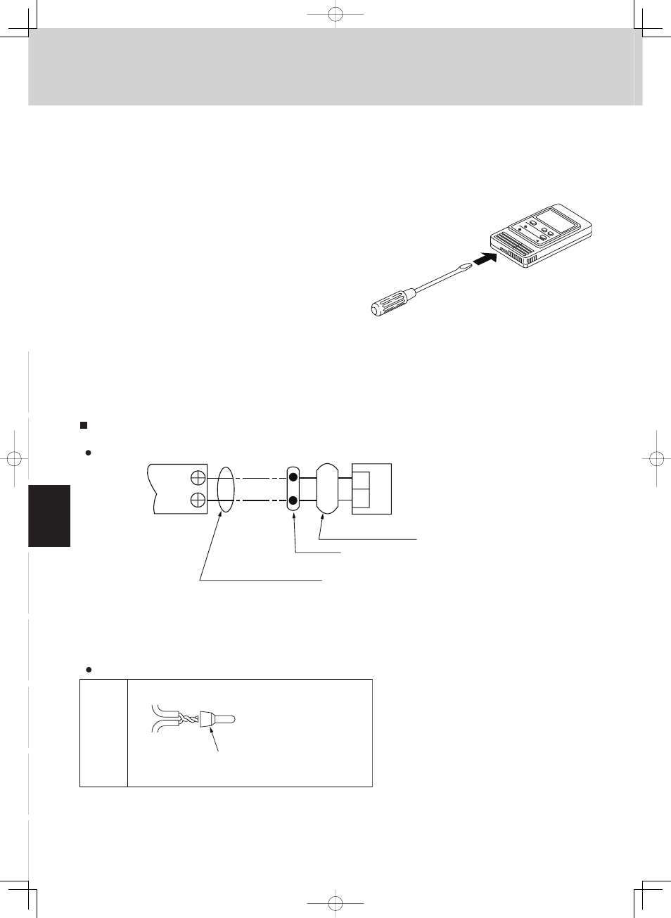
5. Simplifi ed Remote Controller
1. Insert a screwdriver or the like in the groove on the lower
side of the simplifi ed remote controller body to pry off the
back case. (Fig. 3-38)
2. Use the 2 supplied M4 or 5/32" machine screws to secure
the simplifi ed remote controller back case. Prior to mount-
ing, clear the cutouts in the back case corresponding to
the holes in the wall box using a screwdriver or the like.
Use the spacers and take care not to tighten the screws
excessively. If the back case will not seat well, cut the
spacers to a suitable thickness.
3. Connect locally supplied 3 core lead wires to the lead
wires from the simplifi ed remote controller. (See “How to
wire the simplifi ed remote controller.”)
When connecting the locally supplied 3 core lead
wires to the terminal block, check the terminal num-
bers in the indoor unit to make sure that the wires are
correctly connected. (Fig. 3-39)
(The simplifi ed remote controller is damaged if 208 /
230 AC is applied.)
4. Fit the simplifi ed remote controller to the tabs of the back
case and mount it.
How to connect lead wires
Fig. 3-38
How to Wire the Simplifi ed Remote Controller
Connection diagram
1. Peel off 35/64” of the
cable sheathing.
2. Twist the 2 wires together
and crimp them together
with the wire joint.
3. When a crimping tool is
not used, solder the wires
together and cover the
joint with insulating tape.
Wire
joint
Lead wire
from simplified
remote controller
Lead wire from
indoor unit
2 supplied
white wire
joints