System design – Sanyo CHX03652 User Manual
Page 28
2-20
Design of Mini ECO-i SYSTEM
1
2
3
4
5
6
7
8
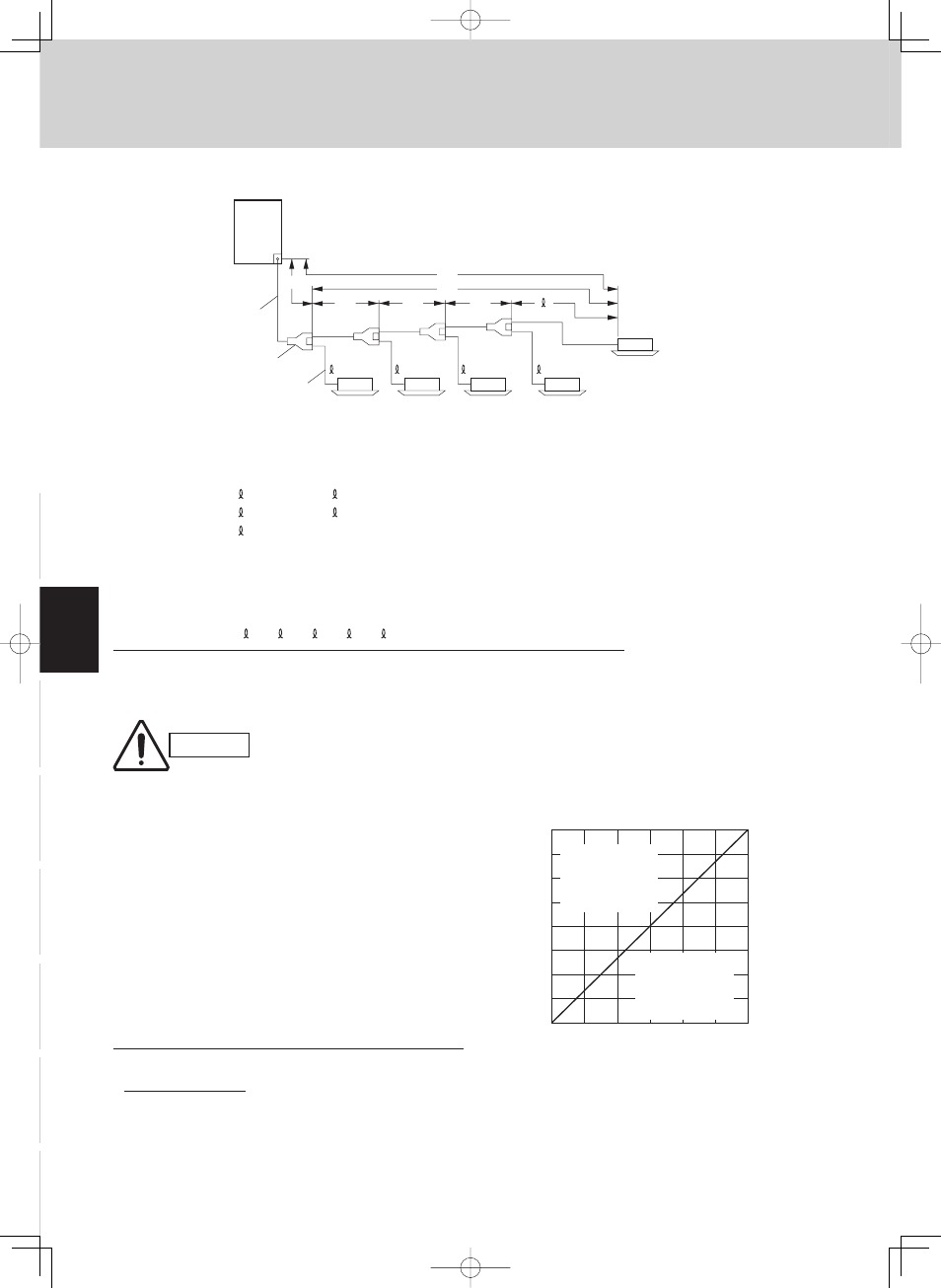
Checking of limit density
Density limit is determined on the basis of the size
of a room using an indoor unit of minimum capacity.
For instance, when an indoor unit is used in a room
(floor area 80 ft
2
× ceiling height 8.8 ft. = room volume
704 ft.
3
), the graph at right shows that the minimum
room volume should be 497 ft.
3
(floor area 56 ft.
2
) for
refrigerant of 147 oz. Accordingly, openings such as
louvers are required for this room.
Overall refrigerant charge amount for the air conditioner: oz
(Minimum room volume for indoor unit: ft.
3
)
=
147 (oz) + 123 (oz)
= 0.38 (oz/ft.
3
)
≥≥ 0.3 (oz/ft
3
)
704 (ft
3
)
Therefore, openings such as louvers are required for
this room.
●
Obtain charge amount for each tubing size
Note that the charge amounts per 3.3 ft. are different for each liquid tubing size.
ш3/8" (ш9.52)
→ LA + LB + LC + LD
: 212 ft.
× 0.602 oz/ft. = 127 oz
ш1/4" (ш6.35)
→ 1 + 2 + 3 + 4 + 5 : 75 ft. × 0.279 oz/ft. = 20 oz
Total
147
oz
Additional refrigerant charge amount is 147 oz.
Be sure to check the limit density
for the room in which the indoor
unit is installed.
CAUTION
●
Example of each tubing length
Main tubing Distribution joint tubing
LA = 131 ft.
Indoor side
LB = 16 ft.
1 = 16 ft.
4 = 20 ft.
LC = 16 ft.
2 = 16 ft.
5 = 16 ft.
LD = 49 ft.
3 = 7 ft.
LN
L1
L2
LC
LB
LA
Main tube of unit
1st branch
model 0752
model 0952
model 1252
model 1852
model 1852
Unit distribution tube
1
2
3
n–1
n
Example:
57
114
170
227
284
341
398
454
0
500
1000
1500
2000
2500
3000
3500
4000
400
200
600
800 1000 1200
Total amount of refrigerant
Min.
indoor v
olume
Min.
indoor floor area
(when the ceiling is 8.8 ft.
high)
ft.
3
ft.
2
oz
Range above
the density limit of
0.3 oz/ft.
3
(countermeasures
needed)
Range below
the density limit of
0.3 oz/ft.
3
(countermeasures
not needed)
0 0
2. System Design