System design – Sanyo CHX03652 User Manual
Page 23
2-15
1
2
3
4
5
6
7
8
Design of Mini ECO-i SYSTEM
2-7. Additional Refrigerant Charge
Additional refrigerant charge amount is calculated from the liquid tubing total length as follows.
Table 2-8 Amount of Refrigerant Charge Per Meter, According to Liquid Tubing Size
Liquid tubing size
Amount of refrigerant
(in. (mm))
charge (oz/ft.)
ш1/4”
(ш6.35)
0.279
ш3/8” (ш9.52)
0.602
Required amount of charge = (Amount of refrigerant
charge per meter of each size of liquid tube × its tube
length) + (...) + (...)
*Always charge accurately using a scale for weighing.
Table 2-9 Refrigerant Charge Amount at Shipment (for outdoor unit)
2-8. System Limitations
Table 2-10 System Limitations
Number of max. connectable indoor units
Outdoor units (Type)
CHX03652
6
CHX06052
9
Max. allowable indoor/outdoor capacity ratio
50 130%
Heat pump unit
(Single-phase)(oz)
CHX03652
123
CHX06052
123
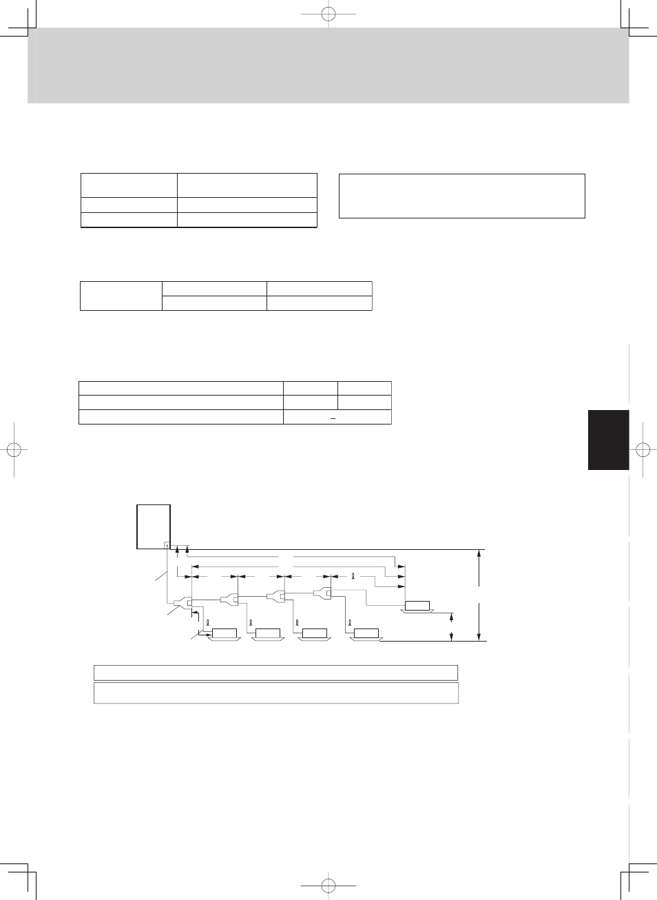
2-9. Tubing Length
R410A distribution joint
APR-P160BA (for indoor unit)
Note: Do not use commercially available T-joints for the liquid tubing.
H2
LD
L1
L2
LC
LB
LA
* Be sure to use special R410A distribution joints (APR: purchased separately) for outdoor
unit connections and tubing branches.
Main tube of unit
1st branch
Unit distribution tube
1
2
3
n-1
n
L3
H1
Select the installation location so that the length and size of refrigerant tubing are within the allowable range shown
in the figure below.
2. System Design