Sanyo KHH2672R / CH2672R User Manual
Technical data & service manual, Split system air conditioner
85464849248002
REFERENCE NO.
SM
831148-2
FILE NO.
TECHNICAL DATA
&
SERVICE MANUAL
1
2
3
4
5
6
Section
XH2672R / CH2672R, C2672R
XH3672R / CH3672R, C3672R
XH4272R / CH4272R, C4272R
TH2672R / CH2672R, C2672R
TH3672R / CH3672R, C3672R
THH2672R / CH2672R
THH3672R / CH3672R
TH4272R / CH4272R, C4272R
KH2672R / CH2672R, C2672R
KH3072R / CH3072R, C3072R
KH3672R / CH3672R, C3672R
KHH2672R / CH2672R
UH2672R / CH2672R, C2672R
UH3672R / CH3672R, C3672R
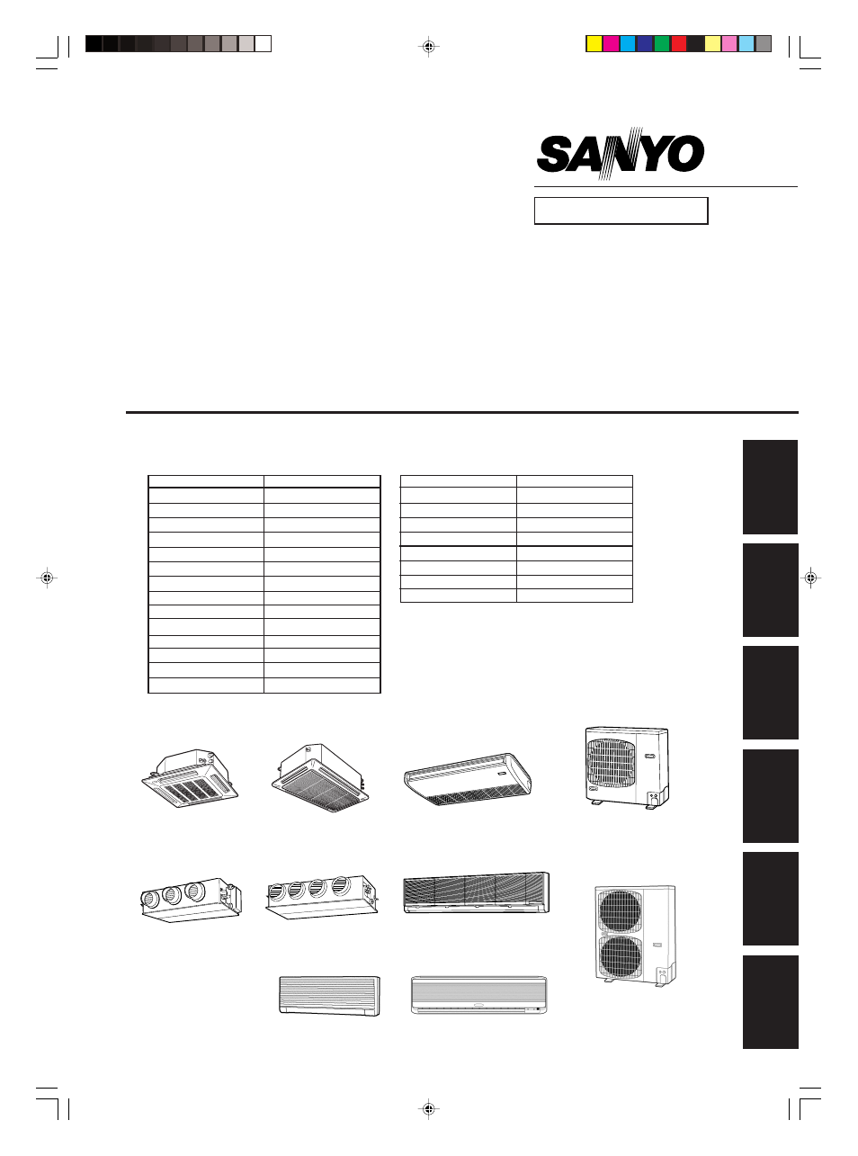
SPLIT SYSTEM AIR CONDITIONER
XH2672R
XH3672R
XH4272R
CH4272R, C4272R
UH2672R
TH2672R, THH2672R
TH3672R, THH3672R
TH4272R
CH2672R, C2672R
CH3072R, C3072R
CH3672R, C3672R
KH3072R
KH3672R
Indoor Unit
Outdoor Unit
UH3672R
KHH2672R
KH2672R
OUTDOOR MODEL No.
PRODUCT CODE No.
CH2672R
854 028 20
CH3072R
854 028 21
CH3672R
854 028 22
CH4272R
854 031 87
C2672R
854 028 24
C3072R
854 028 25
C3672R
854 028 26
C4272R
854 031 88
INDOOR MODEL No.
PRODUCT CODE No.
XH2672R
854 028 32
XH3672R
854 028 33
XH4272R
854 031 89
TH2672R
854 028 35
TH3672R
854 028 36
TH4272R
854 031 90
THH2672R
854 028 38
THH3672R
854 028 39
KH2672R
854 028 28
KH3072R
854 028 29
KH3672R
854 028 30
KHH2672R
854 028 31
UH2672R
854 028 40
UH3672R
854 028 41
Document Outline
- SM831148-02_08
- TECHNICAL DATA & SERVICE MANUAL
- Important
- Contents
- 1.SPECIFICAITONS
- 1-1.Unit Specifications
- 1-2.Major Component Specifications
- 1-3.Other Component Specifications
- 1-4.Dimensional data 1/2
- 1-4.Dimensional data 2/2
- 1-5.Refrigerant Flow Diagram
- 1-6.Operating Range
- 1-7.Heating Capacity
- 1-8.Noise Criterion Curves 1/2
- 1-8.Noise Criterion Curves 2/2
- 1-9.Increasing the Fan Speed
- 1-10.Air throw distance chart
- 1-11.Installation Instructions
- 1-12.Electrical Wiring
- 1-13.Using Wireless Remote Controller with Wall-mounted Indoor Unit
- 2.PROCESSES AND FUNCTIONS
- 2-1.Room Temperature Control
- 2-2.Cold Draft Prevention (Heating Cycle)
- 2-3.Automatic Fan Speed (Indoor Unit)
- 2-4.Control Functions
- 2-5.Outdoor Unit Control PCB
- 2-6.Outdoor Unit Control PCB (CR-CH4272R)
- 3.ELECTRICAL DATA
- 3-1.Indoor Units 1/2
- 3-1.Indoor Units 2/2
- 3-2.Outdoor Units
- 4.SERVICE PROCEDURES
- 4-1.Meaning of Alarm Meassages
- 4-2.Symptoms and Parts to Inspect
- 4-3.Details of Alarm Meassages
- 5.OUTDOOR UNIT MAINTENANCE REMOTE CONTROL
- 5-1.Overview
- 5-2.Functions
- 5-3.Normal Display Operations and Functions
- 5-4.Monitoring Operations: Display of Indoor Unit and Outdoor Unit Sensor Temperatures
- 5-5.Monitoring the Outdoor Unit Alarm History: Display of Outdoor Unit Alarm History
- 5-6.Setting Modes: Setting the Outdoor Unit EEPROM
- 6.TEST RUN
- 6-1.Preparing for Test Run
- 6-2.Caution
- 6-3.Test Run Procedure
- 6-4.Items to Check Before the Test Run
- 6-5.Test Run Using the Remote Controller
- 6-6.Precautions
- 6-7.Table of Self-Diagnostic Functions and Corrections (X,T,U,K Type)
- 6-8.Examples of Wiring Diagrams
- SM831148-02_18
- TECHNICAL DATA & SERVICE MANUAL
- 1.SPECIFICAITONS
- SM831148-02_28
- TECHNICAL DATA & SERVICE MANUAL
- 1-4.Dimensional data 1/2
- 1-4.Dimensional data 2/2
- 1-5.Refrigerant Flow Diagram
- 1-6.Operating Range
- 1-7.Heating Capacity
- 1-8.Noise Criterion Curves 1/2
- 1-8.Noise Criterion Curves 2/2
- TECHNICAL DATA & SERVICE MANUAL
- SM831148-02_38
- TECHNICAL DATA & SERVICE MANUAL
- 1-8.Noise Criterion Curves 1/2
- 1-8.Noise Criterion Curves 2/2
- 1-9.Increasing the Fan Speed
- 1-10.Air throw distance chart
- 1-11.Installation Instructions
- TECHNICAL DATA & SERVICE MANUAL
- SM831148-02_48
- SM831148-02_58
- TECHNICAL DATA & SERVICE MANUAL
- 3.ELECTRICAL DATA
- 3-1.Indoor Units 1/2
- 3-1.Indoor Units 2/2
- SM831148-02_68
- TECHNICAL DATA & SERVICE MANUAL
- 3-1.Indoor Units 1/2
- 3-1.Indoor Units 2/2
- TECHNICAL DATA & SERVICE MANUAL
- SM831148-02_78
- SM831148-02_88
- TECHNICAL DATA & SERVICE MANUAL
- 6.TEST RUN