System design – Sanyo CHX03652 User Manual
Page 22
2-14
Design of Mini ECO-i SYSTEM
1
2
3
4
5
6
7
8
Material
O
Copper tube
Outer diameter
1/4 (6.35)
3/8 (9.52)
1/2 (12.7)
5/8 (15.88)
3/4 (19.05)
Wall thickness
1/32 (0.8)
1/32 (0.8)
1/32 (0.8)
5/128 (1.0)
over 5/128 (1.0)
Table 2-7 Required Copper Tubing Dimensions
Unit: in. (mm)
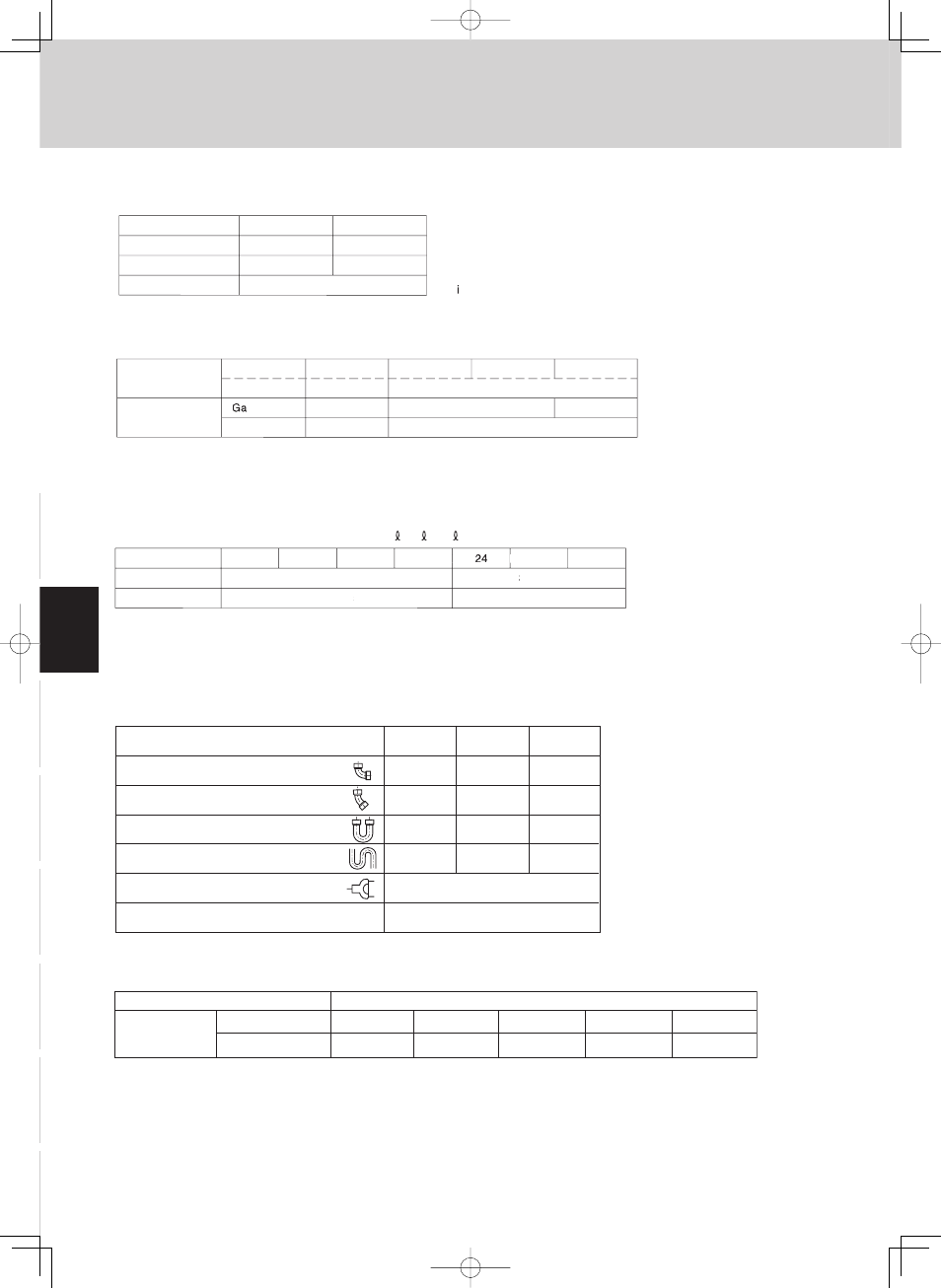
Gas tubing size (in. (mm))
90
° elbow
45
° elbow
Trap bend
1/2" (12.7)
1
0.8
3
7.5
5/8" (15.88)
1.1
0.9
3.4
9.2
3/4" (19.05)
1.4
1
4.1
10.5
Y-branch distribution joint
Ball valve for service
U-shape tube bend (R2-3/8" – 4" (60 – 100))
Equivalent length conversion not needed.
Equivalent length conversion not needed.
2-6. Straight Equivalent Length of Joints
Design the tubing system by referring to the following table for the straight equivalent length of joints.
Table 2-6 Straight Equivalent Length of Joints
Unit: ft.
Table 2-5 Indoor Unit Tubing Connection (
1
,
2
...
n–1
)
ш
5/8
// " (
ш
15.88)
ш
1/2" (
ш
12.7)
ш
1/4" (
ш
6.3
. 5)
ш
3/8" (
ш
9.52)
7
9
12
18
36
48
Indoor unit type
Gas tubing
Liquid tubing
Unit: in. (mm)
24,200 (2.5 hp)
ш
5/
8" (ш15.88)
ш
1/2" (
ш
12.7)
ш
3/4" (ш19.05)
ш
3/8" (ш9.52)
ш
3/8" (ш9.52)
24,200 (2.5 hp)
–
38,200 (4 hp)
47,800 (5 hp)
52,900 (6 hp)
Below BTU/h
Over BTU/h
Tubing size
Total capacity
after distribution
s tubing
Liquid tubing
hp = horsepower
Unit: in. (mm)
2-5. Tubing Size
Table 2-3 Main Tubing Size (LA)
ш
3/4" (ш19.05)
6
Unit: n. (mm)
52,900 (15.5)
ш
3/8" (ш9.52)
ш
5/
8" (ш15.88)
4
38,200 (11.2)
BTU/h (kW)
System horsepower
Gas tubing
Liquid tubing
Table 2-4 Main Tubing Size After Distribution (LB, LC...)
Note: In case the total capacity of connected indoor units exceeds the total capacity of the outdoor units, select the main
tubing size for the total capacity of the outdoor units.
2. System Design