Installation instructions, Design of mini eco-i system – Sanyo CHX03652 User Manual
Page 34
2-26
Design of Mini ECO-i SYSTEM
1
2
3
4
5
6
7
8
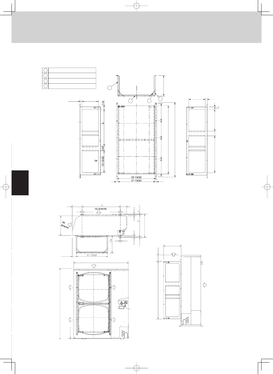
3-6. Dimensions of Air-Discharge Chamber
Reference diagram for air-discharge chamber (field supply)
CHX03652/06052
9-7/16
1-1/8
1-1/8
/8
2
1-
5/
2
Rectangular
hole
Rectangular
hole
Rectangu
hole
Rectangular
hole
11
-1
3
/1
6
2
1
4
3
9-7/16
1
-3
/8
12-1
5/
3
2
2
1-
5/
3
2
2-
3/
4
4
2-2
9/
3
2
3
9
-1
/4
9
-27
/3
2
9
-27
/3
2
1
2-7
/3
2
9
-27
/3
2
Unit: in.
1
1
1 Unit front, air discharge chamber
2 Unit left side, air discharge chamber
3 Unit light side, air discharge chamber
4 Reinforcement brackets, 4 locations
4-5/16
25-3 32
6-11/16
1/2
1/2
1
3
3
/8
15
-1
5/
1
6
14
-3
1/
3
3
/3
2
1
9/
3
2
25/
3
2
25/
3
2
1/2
2-11/36
11
-1
3
nd
n
Wi
n
37
2
3
/3
2
4
8
-7
/1
6
Wind
direction
Wind
direction
Wind
direction
Wind
direction
11-13/16
4-1/4
39-1/4
Wind direction
Wind direction
Unit: in.
3-7. Dimensions of Outdoor Unit with Air-Discharge Chamber (field supply)
CHX03652/06052
3. Installation Instructions