Remote sensor – Sanyo CHX03652 User Manual
Page 109
3-65
Control of Mini ECO-i SYSTEM
1
2
3
4
5
6
7
8
6. Remote Sensor
How to Install the Remote Sensor
because this may cause malfunction.
< NOTE 2 > Install the remote sensor away from sources of electrical noise.
< NOTE 3 > Install a noise fi lter or take other appropriate action if electrical noise affects the power supply
circuit of the unit.
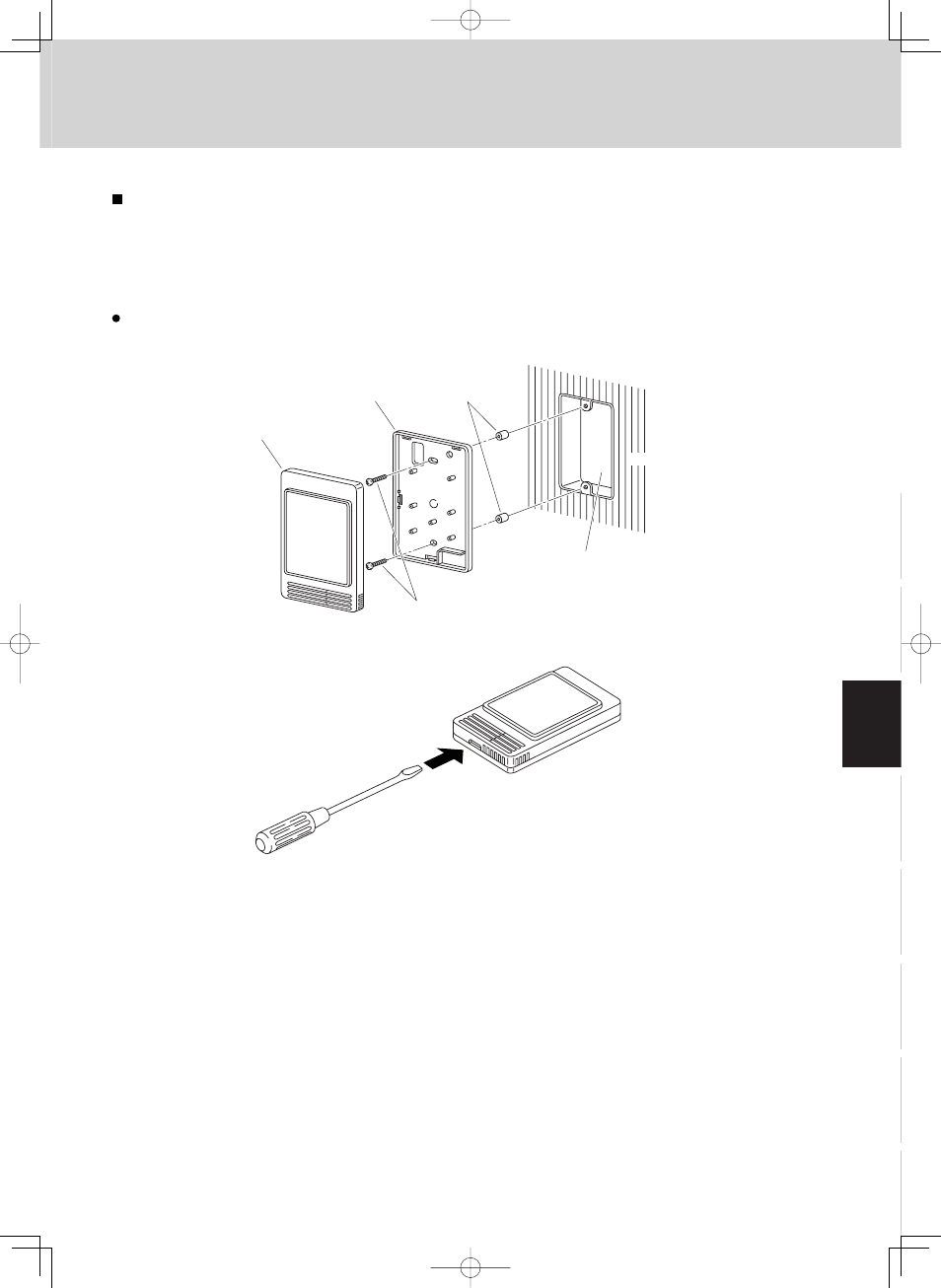
Use an electric junction box (supplied locally) (Fig. 3-43) for fl ush mounting of the remote sensor.
Fig. 3-43
Simplified remote controller
Under case (back case)
Spacer
Machine screws
M4
×
25 or 5/32”
×
1”
Electric junction box
for one box (no cover)
Wall
Fig. 3-44
1. Insert a screwdriver or the like in the groove on the lower side of the remote sensor body to pry off the
back case. (Fig. 3-44)
2. Use the 2 supplied M4 or 5/32" machine screws to secure the remote sensor back case. Prior to
mounting, clear the cutouts in the back case corresponding to the holes in the wall box using a screw-
driver or the like. Use the spacers and take care not to tighten the screws excessively. If the back case
will not seat well, cut the spacers to a suitable thickness.
3. Connect locally supplied 2 core lead wires to the lead wires from the remote sensor. (See “How to wire
the remote sensor.”)
When connecting the locally supplied 2 core lead wires to the terminal block, check the termi-
nal numbers in the indoor unit to make sure that the wires are correctly connected. (Fig. 3-45)
(The remote sensor is damaged if 208 / 230V AC is applied.)
4. Fit the remote sensor to the tabs of the back case and mount it.