Wireless remote controller – Sanyo CHX03652 User Manual
Page 59
3-15
1
2
3
4
5
6
7
8
Control of Mini ECO-i SYSTEM
Fig. 3-13
1
3
2
4
6
5
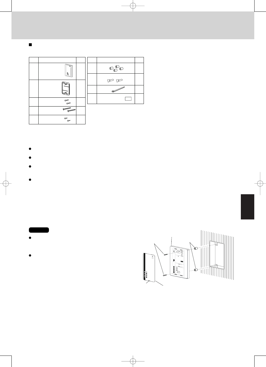
Face plate
Remove
Screws
M4
×
25 or 5/32”
×
1”
Receiver unit
Spacer
2
(provided 7-7/8”
power cable)
Plate
mounting
Screws
M4
Ч
Ч
1”
25 or 5/32”
Screws
M4
Ч
1-37/64”
Ч
40 or 5/32”
Wood
screws
1
2
3
4
5
No.
Parts
Q'ty
No.
6
7
8
9
1
1
2
Parts
Q'ty
4
2
1
1
Separate
receiver unit
Spacer
Wire joints
Clamp
Pattern template
3-47/64”
×
2”
2
unit: in
2. Wireless Remote Controller
RCS-BH80AAB.WL for Concealed Duct(U Type) and Concealed Duct High-Static Pressure(Type D)
2-11. Accessories Supplied with Separate Receiver Unit
2-12. Important Information for Installation of 1
Separate Receiver Unit
Do not install in a location where the air contains oil mist,
such as in a kitchen or factory.
Do not install next to a window, or in any other location
directly exposed to sunlight and outside air.
Do not install nearby devices which can be expected to
produce electrical noise, such as elevators, automatic
doors, and industrial sewing machines.
If the receiver unit is installed near a rapid-start type or
inverter-type fluorescent lamp (a lamp which does not
include a glow lamp), it may not be possible to receive
the wireless remote controller signal in some cases. In
order to prevent interference from fluorescent lamps, leave
a minimum of 6.6 ft between the receiver unit and the
fluorescent lamps, and install the receiver unit in a location
where it can receive the wireless remote controller signal
when the fluorescent lamps are lit.
2-13. How to Install the Separate Receiver Unit
To avoid malfunction of the remote controller, do not
assemble or run remote control wiring together with the
power cables, and do not enclose them in the same metal
conduit.
When the power unit induces electrical noise, it is
recommended that a noise filter or the like be installed.
NOTE