Maxim Integrated DS33R11 User Manual
Page 150
DS33R11 Ethernet Mapper with Integrated T1/E1/J1 Transceiver
150 of 344
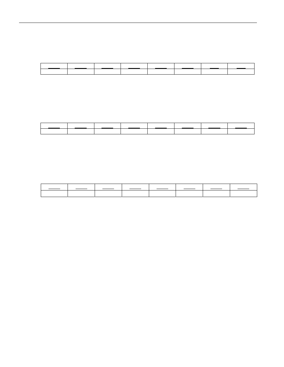
Register Name:
RBCB1
Register Description:
Receive Bit Count Byte 1 Register #1
Register Address:
99h
Bit
# 7 6 5 4 3 2 1 0
Name
BC15
BC14
BC13
BC12
BC11
BC10
BC9
BC8
Default
0 0 0 0 0 0 0 0
Bits 0 - 7: Bit Count (BC[8:15]) Eight bits of a 32 bit value. Register description below.
Register Name:
RBCB2
Register Description:
Receive Bit Count Byte 2 Register
Register Address:
9Ah
Bit
# 7 6 5 4 3 2 1 0
Name
BC23
BC22
BC21
BC20
BC19
BC18
BC17
BC16
Default
0 0 0 0 0 0 0 0
Bits 0 - 7: Bit Count (BC[16:23]) Eight bits of a 32 bit value. Register description below.
Register Name:
RBCB3
Register Description:
Receive Bit Count Byte 3 Register
Register Address:
9Bh
Bit
# 7 6 5 4 3 2 1 0
Name
BC31
BC30
BC29
BC28
BC27
BC26
BC25
BC24
Default
0 0 0 0 0 0 0 0
Bits 0 - 7: Bit Count (BC[24:31]) Upper 8-bits of the register.
Bit Count (BC[0:31]) These thirty-two bits indicate the number of bits in the incoming data stream. This count
stops incrementing when it reaches a count of FFFF FFFFh. The associated bit counter will not incremented when
an OOS condition exists.