Introduction, Installation procedure – Multi-Tech Systems MR9600 User Manual
Page 16
MR9600 User Guide
8
CommPlete Communications Server
Introduction
This chapter describes how to install the MR9600 Controller into a CommPlete Communication Server
CC9600 chassis. This equipment should only be installed by properly qualified service personnel.
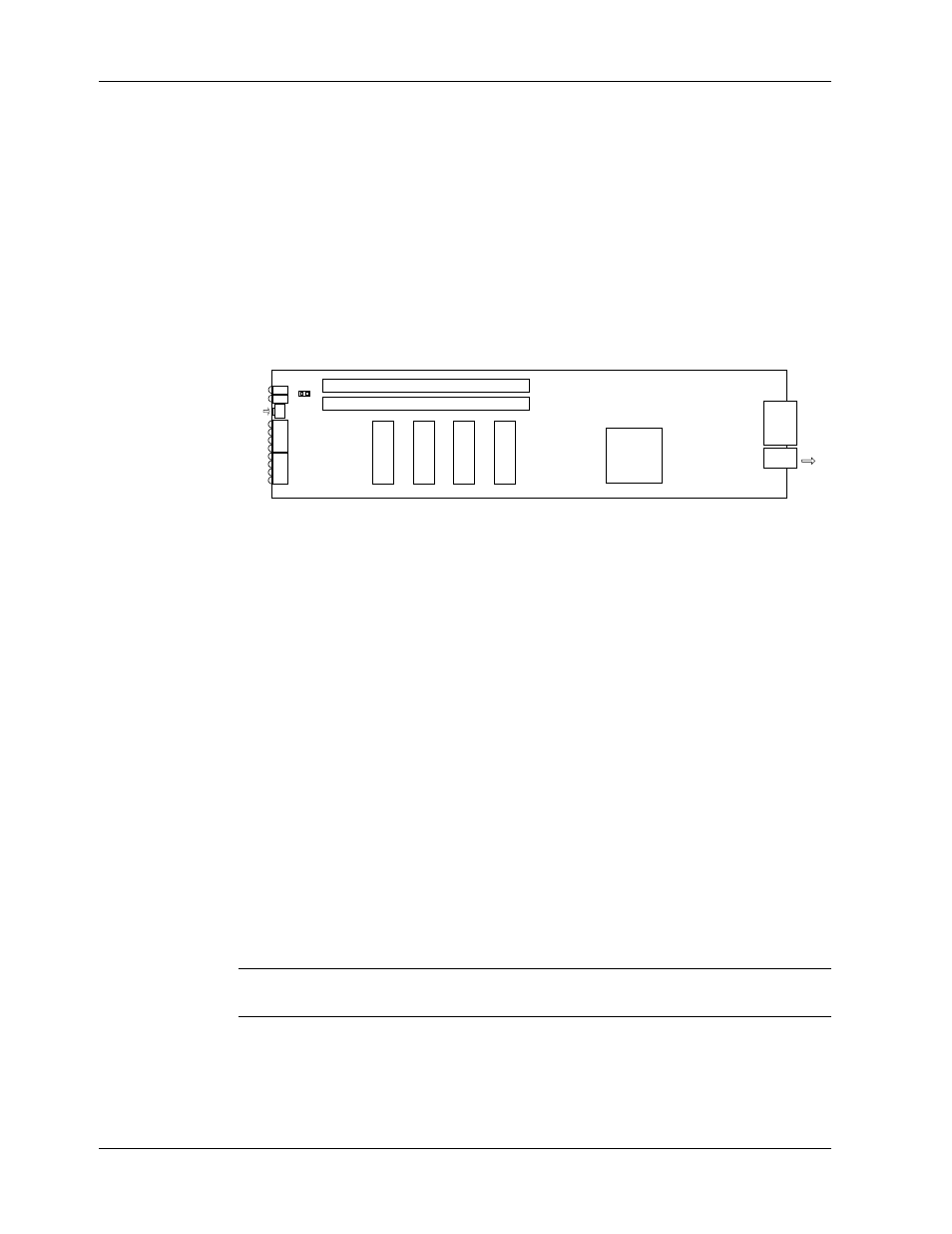
The MR9600 Controller assembly consists of the MR9600 Controller card, an integrated Ethernet
concentrator card, and a common front panel. Figure 3 shows the layout of the MR9600 card without the
concentrator. The MR9600 assembly plugs into bus connectors on the inside of the CC9600 chassis. Three
communications connectors on the concentrator module are accessible from the back of the CC9600
chassis: a DB-9 serial connector for MR9600 diagnostics and configuration, and two Ethernet 10Base-T
connectors for network access.
Connectors
CPU
Flash Memory
U4
U5
U7
U6
LEDs
To
back
panel
config/
debug
port
Reset
RAM
RAM
Test
Figure 3. MR9600 Controller card. Ethernet concentrator module not shown.
Installation Procedure
1. Unpack the MR9600 assembly from its packaging, and save the packaging for possible future use.
Perform a visual inspection of the MR9600. If you are concerned about the condition of the MR9600,
call Technical Support for instructions.
2. Remove the blank controller panel or previous MR9600 controller from the CC9600 chassis. The
MR9600 is hot-swappable.
3. Holding the MR9600 by its handle and the edges of the bottom panel, place the MR9600 into the
open controller slot of the CC9600. Make sure the edges of the MR9600 card mate properly with the
plastic guides in the CC9600.
4. Slide the MR9600 into the CC9600 chassis until you feel the MR9600’s connectors fit into the bus
connectors at the back of the CC9600.
5. Tighten the MR9600's retaining screws.
6. Turn on the PS9600 power supplies, if they are off.
7. Note the PS9600 LED indicators. If they are not lit, see Chapter 6. If they are lit, proceed with
MultiCommManager operation (Refer to the MultiCommManager User Guide).
Note:
A self-test runs each time the CommPlete Communications Server is turned on. Refer to the
MultiCommManager User Guide for more details on the power-on self-test.