Cutting a zero clearance insert – Grizzly G0696X User Manual
Page 42
g0605X1-6X1, g0696X-97X (mfg. 8/11+)
-39-
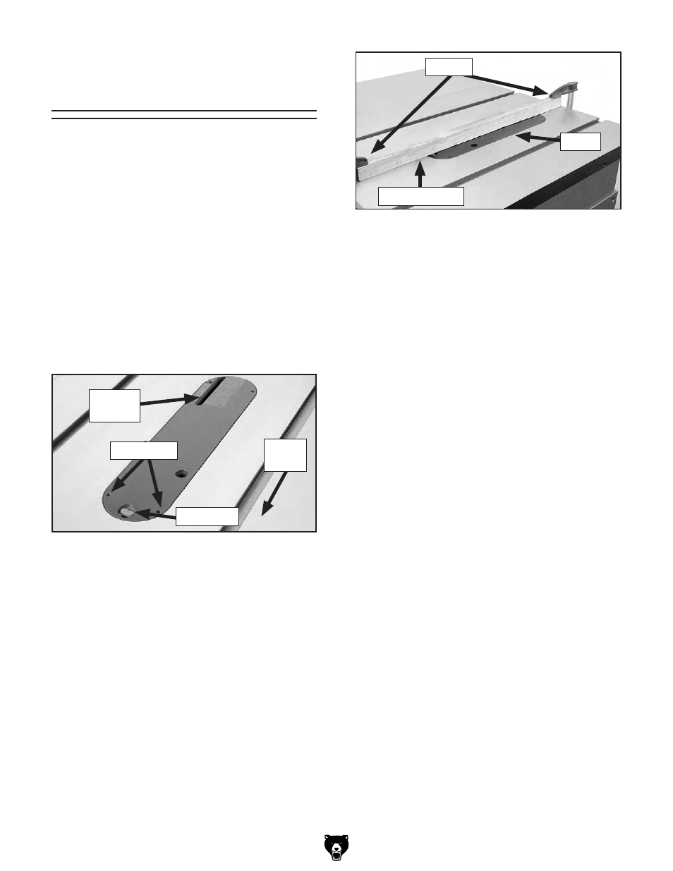
5. Center a board at least 2" thick and equal to
the length of the table over the rear open-
ing of the insert, then secure it with clamps
at both ends, as shown in
Figure 72. this
will provide extra support for the insert and
reduce tear out when cutting.
6. set the blade angle at 0°.
Suggestion: To retain the zero clearance
ability of the insert included with this saw, we
recommend only raising the blade into the
insert at 90° during the following step.
— if you need a zero clearance insert for
compound cuts, install an optional phenolic
zero clearance table insert, model t21879
(refer to
page 58) for each angled cut, then
proceed to
Step 7.
—
if you plan to use a dado blade to cut rab-
bets or dados, install the optional dado
table insert, model t21878 (see
page 58).
— if you do not require your insert to have a
zero clearance fit, especially if you need to
make a range of compound cuts, you can
modify the insert included with this saw.
Continue with
Step 7, then route the under-
side of the blade-cut slot to the same width
as the rear opening (see
Figure 71).
7. Connect the saw to power. Keep hands off
of table top, do not stand directly behind the
blade path, and wear eye protection.
8. turn the saw ON, then slowly raise the blade
to the maximum height that will be used dur-
ing normal operations.
9. turn the saw OFF, lower the blade complete-
ly, then remove the board and clamps.
10. install the blade guard (refer to "installing
Blade guard & spreader" on
page 35).
Figure 72. securing insert with board and
clamps.
Clamps
2" thick Board
insert
cutting a zero
clearance Insert
A zero clearance insert is provided with the table
saw to reduce workpiece tear out and increase
user safety. the insert can be customized to fit a
specific blade height or blade angle for the appli-
cable cutting operation.
To install the zero clearance insert:
1. disConnECt sAW From poWEr!
2. Check to make sure the blade is properly
installed (refer to the instructions in
Blade
Installation on page 34).
3. install the table insert, as shown in Figure
71.
4. Adjust the table insert set screws with a
2.5mm hex wrench to make sure the insert is
flush with the table (use a straightedge as a
guide), then turn the lock knob to secure the
insert.
Figure 71. insert knob in lock position.
lock Knob
rear
opening
set screws
Front
of saw