Grizzly G0696X User Manual
Page 25
-22-
g0605X1-6X1, g0696X-97X (mfg. 8/11+)
5. Use a straightedge as a gauge and adjust the
extension wing up/down until it is flush with
the main table above each bolt, then com-
pletely tighten all the bolts.
6. place the long straightedge across the exten-
sion wings and main table to make sure that
the combined table surface is flat.
—if the combined table surface is flat, skip to
the next step.
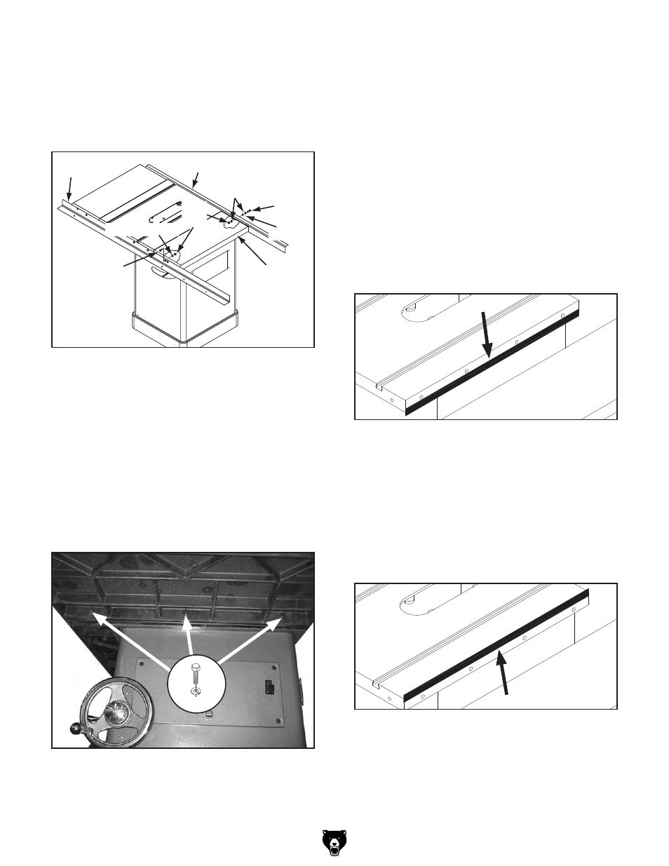
—if the outside end of the extension wing tilts
down, use a strip of masking tape along the
bottom edge of the main table to shim the
extension wing up (see
Figure 26).
Figure 26. masking tape location for tilting the
extension wing up.
— if the outside end of the extension wing
tilts up, use a strip of masking tape along
the top edge of the main table to shim the
extension wing down (see
Figure 27).
Note: After re-installing wings, remove all
excess masking tape with a razor blade.
Figure 27. masking tape location for adjusting
the extension wing down.
2. With the assistance of a helper, place the
extension wing between the rails, and fasten
the wing to the front rail with (1) m8-1.25 x
25 flat head screw, 8mm lock washer and
m8-1.25 hex nut (see
Figure 24). Finger
tighten for now.
Lock
Washers
Rear Rail
Front Rail
Extension
Wing
Cap
Screw
Flat Head
Screw
Hex
Nuts
Lock Washer
Flat
Washer
Figure 24. Extension wing attached to model
g0696X/g0697X.
3. Attach the extension wing to the rear rail
with (1) m8-1.25 x 25 cap screw, (2) 8mm
lock washers, (1) 8mm flat washer and (1)
m8-1.25 hex nut, as shown in
Figure 24.
Finger tighten for now.
4. Attach the cast iron wing to the main table
with (3) m10-1.5 x 35 hex bolts and 10mm
lock washers, as shown in
Figure 25. Finger
tighten for now.
Figure 25. Extension wing installed.
x3
7. Follow the on/oFF switch instructions on
page 25.