Operator’s manual – Great Plains DICKEY-john Seed Manager SE Operator Manual User Manual
Page 33
OPERATOR’S MANUAL
Seed Manager SE
11001-1359A-200810
STARTUP / 31
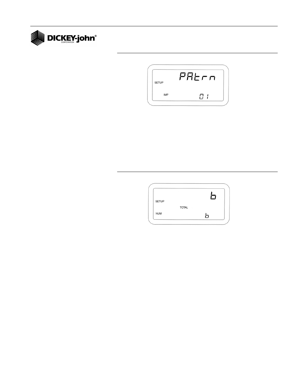
Figure 26
Pattern Select Display
NOTE: Use (
Figure 16
) Setup Mode
Parameters as reference for the
following items numbered 1-21
10. NUMBER OF SEED MODULES
This is the actual number of seed modules that are connected to the
system. Note: This does not include the shaft speed module if one is
available on the system. This parameter will be checked as part of the
Sensor/Module Self-Test and error codes generated if this value does not
match the actual number of seed modules. (
Figure 27
) shows a
configuration for six (6) modules.
Figure 27
Seed Modules Display
10A-E. Number of Seed Sensors Per Module
For each seed module that is configured on the previous Setup screen,
there will be a Number of Seed Sensors per Module screen. This is the
actual number of seed sensors that are connected to the particular module.
The modules are numbered from the far left of the implement (end of P1) to
the far right of the implement (end of P2). This parameter will be checked
as part of the Sensor/Module Self-Test and error codes will be generated if
this value does not match the actual number of seed sensors. (
Figure 28
)
shows twelve (12) seed sensors configured on module 3.