Operator’s manual – Great Plains DICKEY-john Seed Manager SE Operator Manual User Manual
Page 30
OPERATOR’S MANUAL
Seed Manager SE
11001-1359A-200810
28 / STARTUP
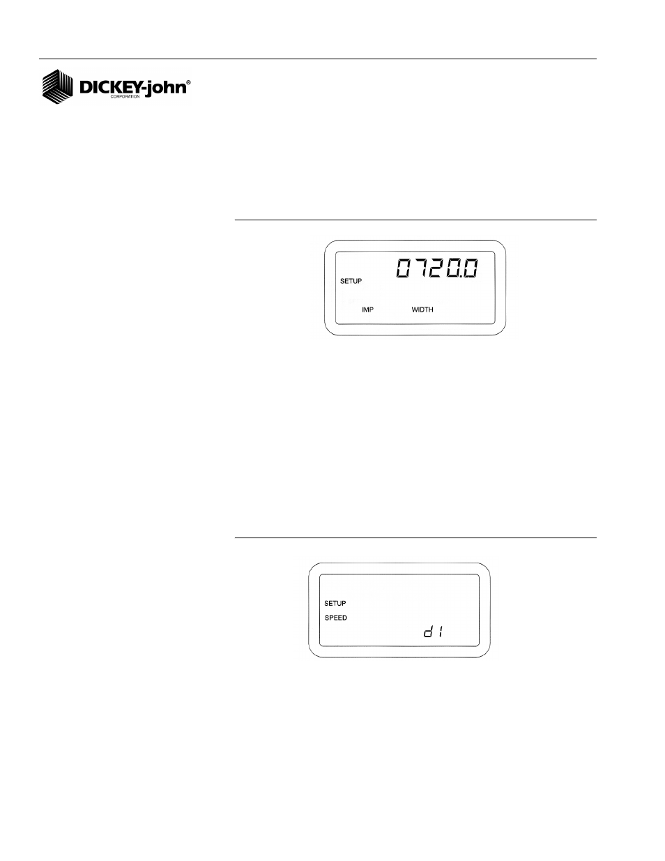
5. IMPLEMENT WIDTH
This is the seeding width of the implement in inches (centimeters) with a
resolution of 0.1. It is automatically calculated when either the Number of
Modules, Number of Rows per Module, or the Row Width is changed and
can be edited for special applications such as skip row seeding. (
Figure 21
)
shows an implement width of 720.0 inches.
NOTE: Use (
Figure 16
) Setup Mode
Parameters as reference for the
following items numbered 1-21.
Figure 21
Implement Width
6. GROUND SPEED SOURCE
Pressing the Set switch causes the lower right display to toggle between
“d1”, “r1”, or “d2”. If a digital (radar or Hall Effect) type ground speed sensor
is used and is connected directly to the Seed Manager
®
Console, press the
SET switch until “d1” appears.
If a digital (radar or Hall Effect) type ground speed sensor is used and is
connected to a Shaft Speed Module, press the SET switch until “d2”
appears. If a reluctance type ground speed sensor is used, press the SET
switch until “r1” appears. (
Figure 22
) shows a configuration for a digital 1
ground speed source.
Figure 22
Ground Speed Sensor Type Display
7. DISTANCE CALIBRATION
The Distance Calibration constant is the number of pulses generated by the
ground speed sensor while traveling a distance of 400 feet (122 meters).
(
Figure 23
) shows the display with the SETUP, SPEED, and COUNT
messages and the default value of 6096 which is the nominal pulse count
for the radar ground speed sensor. A smaller number, typically 3100,
results with a reluctance ground speed sensor.