HT instruments GEO416 User Manual
Page 28
GEO416
-
GEO416GS
EN - 27
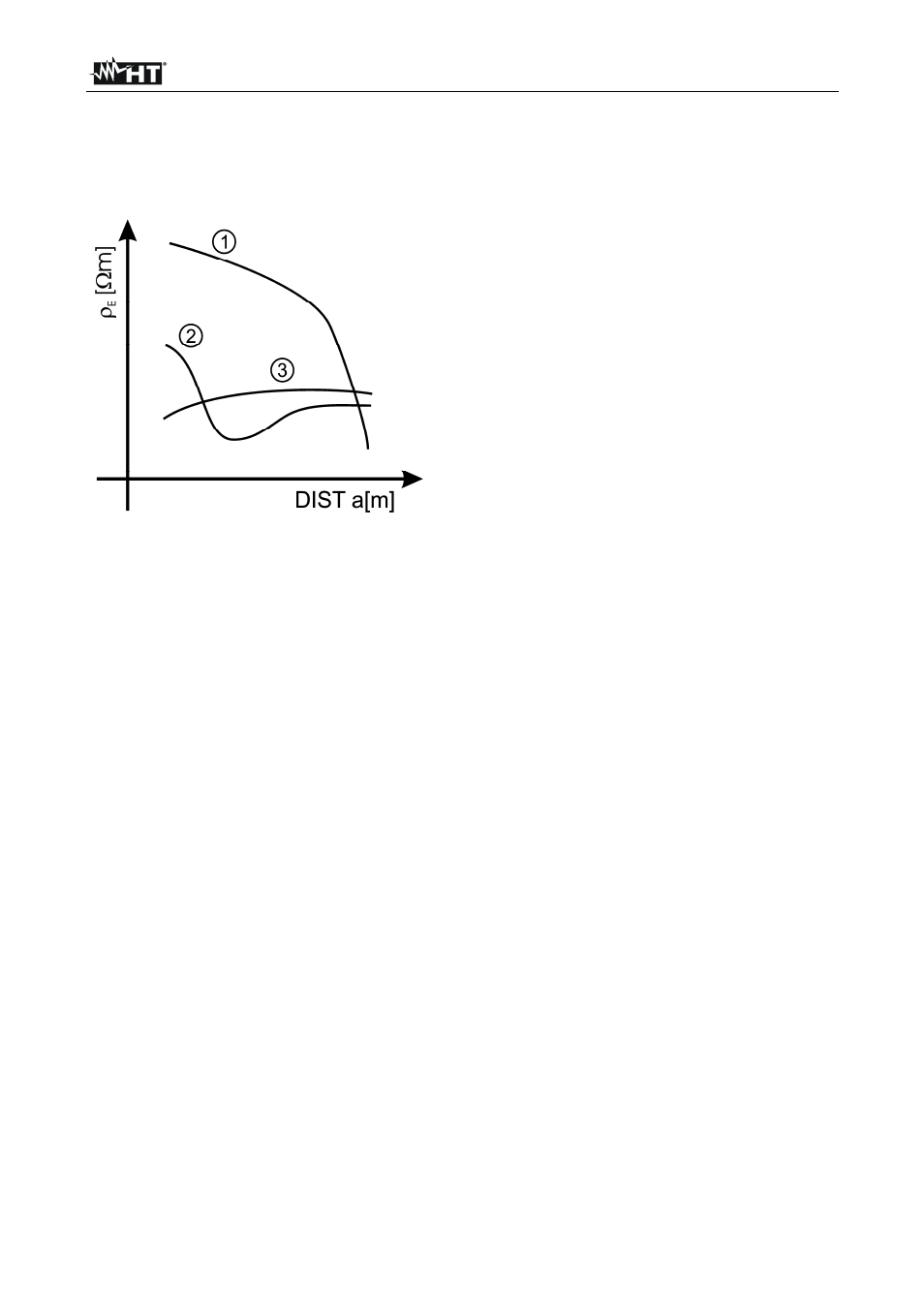
The measuring method allows defining the specific resistivity of a ground layer up to the
depth corresponding approximately to the distance “a” between the rods. If you increase
the distance “a” you can reach deeper ground layers and check the ground homogeneity.
After several measurements you can trace a profile according to which the most suitable
rod is chosen.
Curve 1: as
decreases only in depth, it’s
advisable to use a very deep rod
Curve 2: as
E
decreases only until the depth
a, it’s not useful to increase the
depth of the rod beyond a
Curve 3:
the ground resistivity is quite
constant, so increasing depth does
not make
E
decrease, therefore a
ring rod must be used
Fig. 10: Measurement of ground resistivity
11.3.1. Approximate evaluation of intentional rods' contribution
The resistance of a rod Rd can be calculated with the following formulas (
= average
resistivity of the ground).
a) resistance of a vertical rod
Rd =
/ L
where L = length of the element touching the ground
b) resistance of an horizontal rod
Rd = 2
/ L
where L = length of the element touching the ground
c) resistance of linked elements
The resistance of a complex system made of more elements in parallel is always higher
than the resistance, which could result from a simple calculation of single elements in
parallel, especially if those elements are close to each other and therefore interactive. For
this reason, in case of a linked system the following formula is quicker and more effective
than the calculation of the single horizontal and vertical elements:
Rd =
/ 4r
where r = radius of the circle which circumscribes the link