FEC AFC1200 User Manual
Page 10
)(& ,QF
2-3b.
The pulldown menu will display three input mode selections:
[FASTENING]
Fastening parameter set screen
[SPEED]
Speed parameter set screen
[REVERSE]
Reverse parameter set screen
2-3c. Using
the
[↑] [↓]
keys, select the desired input mode and depress the
[↵]
key. The selected input mode screen will now be displayed.
FIG. 7-1-2-3 set parameter [INPUT MODE]
7.1.3 Fastening Parameter Setup
The function of this screen is to preset the following parameters:
Fastening method
Yield (control values)
Tool type
Yield (monitor values)
Torque (control values)
Torque rate (monitor values)
Torque (monitor values)
Angle (control values)
Angle (monitor values)
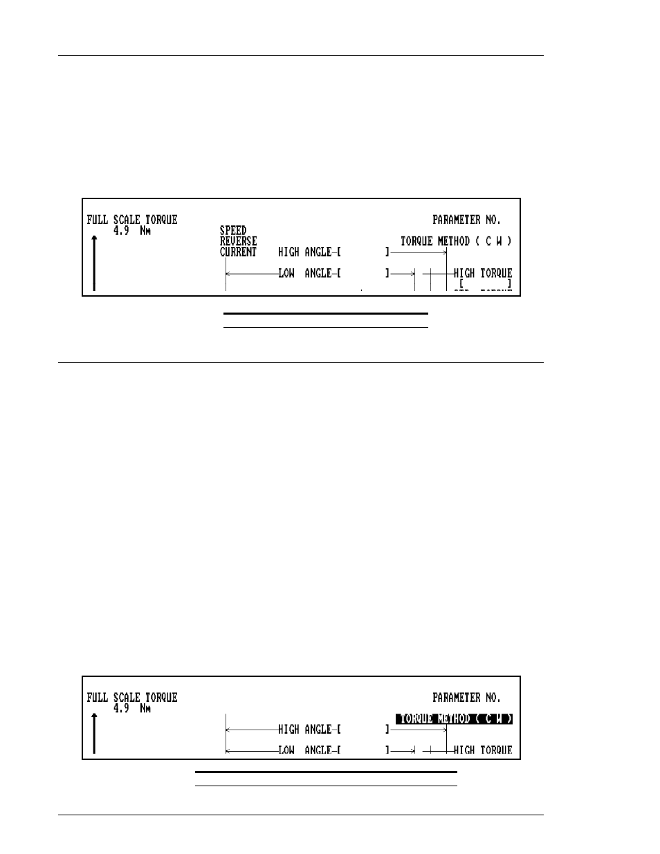
3-1.
Select Fastening Method
3-1a. Move the cursor on the menu bar to [INPUT MODE], select [FASTENING] and
depress the
[↵]
key. The screen displayed will be the "SET PARAMETER
(FASTENING)" screen. (Check the PARAMETER No. to ensure the correct number
has been selected).
3-1b. Depress the [SEL] key. The fastening method will be highlighted. Use the
[←]
[→]
keys to scroll through the fastening method options and depress the
[↵]
key to
select an option. The screen will change to the "SET PARAMETER (FASTENING)"
screen for the selected fastening method.
NOTE: Clockwise (CW) or counterclockwise (CCW) fastening is chosen as part of the fastening
method.
For Angle Method, three (3) options are available: CCW, CW SNUG and CW SEAT.
Typically, SNUG method should be chosen for a clockwise fastening. (SEAT method is
primarily used in Systems operating outside of the United States.)
FIG. 7-1-3-1 set parameter Fastening method selection
Chapter 7: System Operation
Page 7-10