1 flush mounting the remote, 2 surface mounting the remote using the bezel, Side view back view – Magnum Energy ME-MR Remote User Manual
Page 9: Bezel side view bezel front view
©2013 Magnum Energy, Inc.
3
2.0 Installation
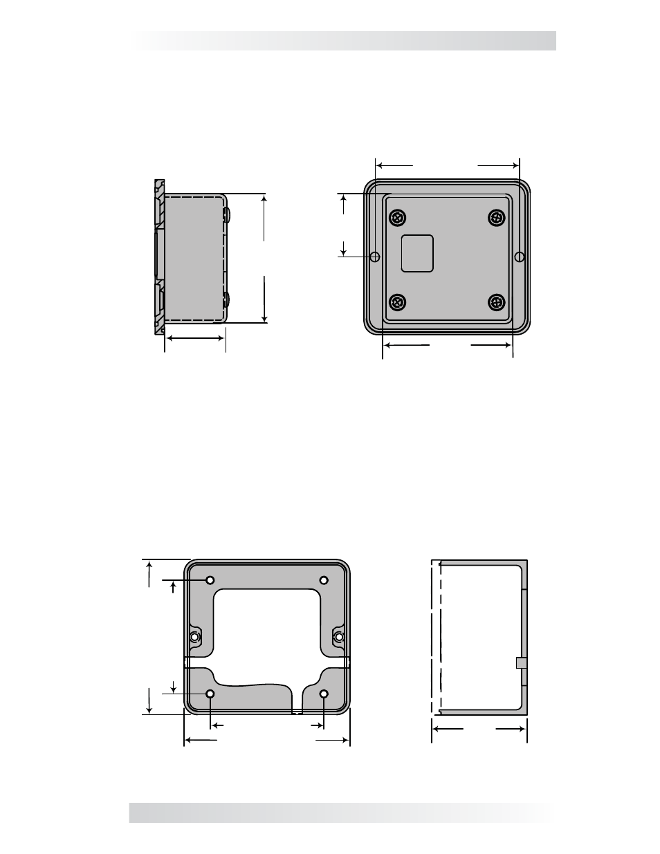
Figure 2-1, Cut-Out Dimensions for Flush Mounted Remote
Figure 2-2, Bezel Dimensions for Surface Mounted Remote
2 ⅜"
1 ⅛"
1 ⅛"
2
11/16
"
(6.03 cm)
(2.86 cm)
2 ⅜"
(6.03 cm)
(2.86 cm)
(6.83 cm)
Side view
Back view
1
⅛
"
2 ⅛" (5.4 cm)
Bezel side view
Bezel front view
(2.86 cm)
3 ⅛" (7.94 cm)
2
⅛
" (5.4 cm)
3
⅛
" (7.94 cm)
2.2.1 Flush Mounting the Remote
After selecting the desired location for fl ush mounting the remote, cut out
a square mounting hole measuring 2
⅜
” x 2
⅜
” (see Figure 2-1). Place the
remote into the cutout, and then use the remote to mark and pre-drill two
⅛
” holes for the two supplied #6 x
½
” Phillips fl at head mounting screws.
2.2.2 Surface Mounting the Remote using the Bezel
After selecting the desired location for surface mounting the remote, use the
bezel (not supplied) as a template to mark the mounting holes. Mark and
pre-drill four
⅛
” holes (see Figure 2-2). Mount the bezel using the four #6
x
¾
” screws.