4 monitoring output signals, 1 interpreting output signal display status, 2 output signal display example – Yaskawa Sigma-5 Large Capacity Users Manual: Design and Maintenance-Command Option Interface User Manual
Page 271: Mecha
7 Monitor Displays (Un
)
7.4.1 Interpreting Output Signal Display Status
7-6
7.4 Monitoring Output Signals
The status of output signals can be checked with the output signal monitor (Un006). The procedure for the
method of interpreting the display and a display example are shown below.
7.4.1 Interpreting Output Signal Display Status
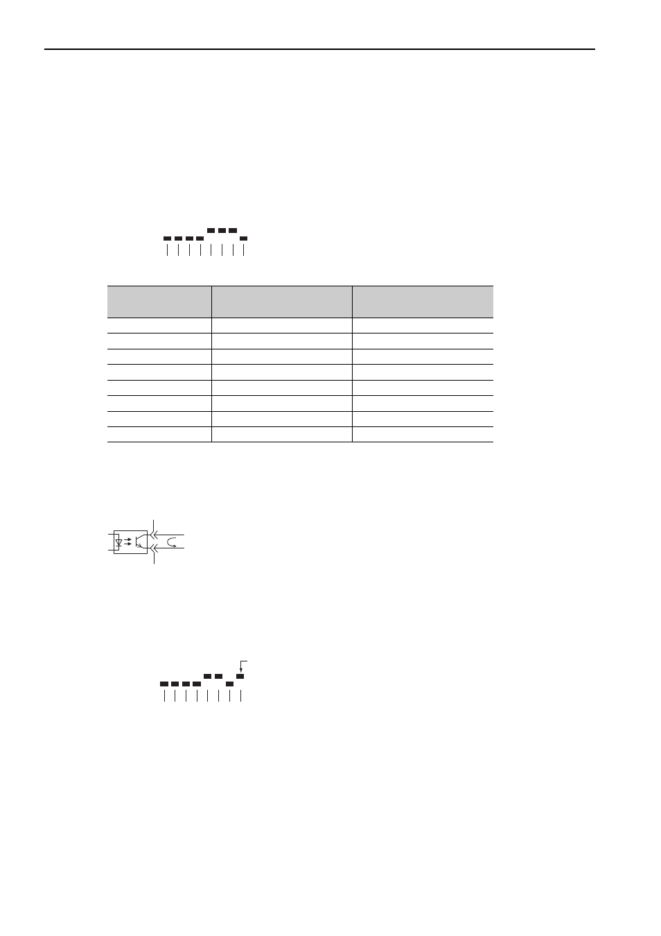
The output signal monitor (Un006) can be read in the following way. The upper level indicates OFF, and the
lower level indicates ON. All undefined digits are shown in the lower level (ON).
Note: Output signals use the following circuit configuration.
• OFF: Transistor OFF
• ON: Transistor ON
Example
7.4.2 Output Signal Display Example
Output signals are displayed as shown below.
• When the ALM signal is OFF
Display LED
Number
Output Terminal Name
Signal Name
(Factory Setting)
1
CN1-31, -32
ALM
2
CN1-25, -26
/BK
3
CN1-27, -28
SO2
4
CN1-29, -30
SO3
5
−
Reserved
6
−
Reserved
7
−
Reserved
8
−
Reserved
U n 0 0 6 =
8 7 6 5 4 3 2 1 digit
MECHA
ON: Transistor ON
U n 0 0 6 =
8 7 6 5 4 3 2 1 digit
The first digit is
in the upper level.
MECHA