3) setting monitor factor, 4) related parameters, Rotation – Yaskawa Sigma-5 Large Capacity Users Manual: Design and Maintenance-Command Option Interface User Manual
Page 166
5.1 Type of Adjustments and Basic Adjustment Procedure
5-7
5
Adjustm
e
nts
(3) Setting Monitor Factor
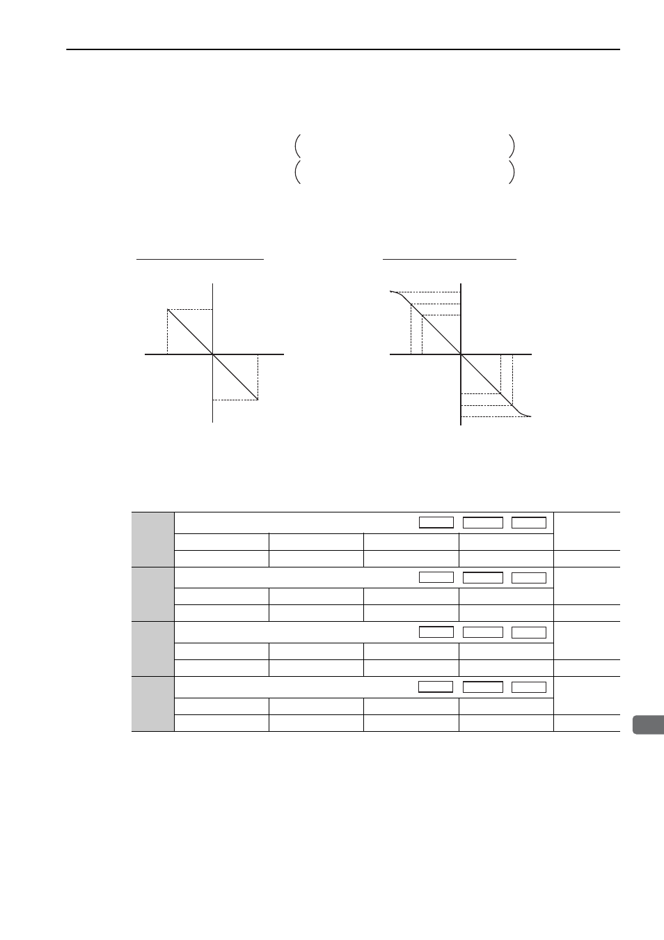
The output voltages on analog monitors 1 and 2 are calculated by the following equations.
Analog monitor output at n.
00 (motor rotating speed setting)
(4) Related Parameters
Use the following parameters to change the monitor factor and the offset.
Analog monitor 1 output voltage = (-1)
×
Analog monitor 2 output voltage = (-1)
×
(Pn006=n.00
)
(Pn552)
(Pn007=n.00
)
Signal selection
×
Multiplier + Offset voltage [V]
(Pn550)
(Pn551)
(Pn553)
Signal selection
×
Multiplier + Offset voltage [V]
+6 V
-6 V
-600
+600
+8 V
-8 V
-800
+800
+10 V (approx.)
-10 V (approx.)
+6 V
-6 V
-6000
+6000
Analog monitor
output voltage [V]
Analog monitor
output voltage[V]
When multiplier is set to
× 1:
When multiplier is set to
× 10:
Motor speed
[min
-1
]
Motor speed
[min
-1
]
Note: Linear effective range: within
± 8 V
Output resolution: 16-bit
Rotation
Pn550
Analog Monitor 1 Offset Voltage
Classification
Setting Range
Setting Unit
Factory Setting
When Enabled
-10000 to 10000
0.1 V
0
Immediately
Setup
Pn551
Analog Monitor 2 Offset Voltage
Classification
Setting Range
Setting Unit
Factory Setting
When Enabled
-10000 to 10000
0.1 V
0
Immediately
Setup
Pn552
Analog Monitor Magnification (
× 1)
Classification
Setting Range
Setting Unit
Factory Setting
When Enabled
-10000 to 10000
× 0.01
100
Immediately
Setup
Pn553
Analog Monitor Magnification (
× 2)
Classification
Setting Range
Setting Unit
Factory Setting
When Enabled
-10000 to 10000
× 0.01
100
Immediately
Setup
Speed
Position
Torque
Speed
Position
Torque
Speed
Position
Torque
Speed
Position
Torque