1) wiring example – Yaskawa Sigma-5 Large Capacity Users Manual: Design and Maintenance-Command Option Interface User Manual
Page 111
4.2 Basic Functions Settings
4-15
4
Ope
rat
ion
∗4. The operation delay time of the brake is shown in the following table. The operation delay time is an example when
the power supply is turned ON and OFF on the DC side. Be sure to evaluate the above times on the actual equipment
before using the application.
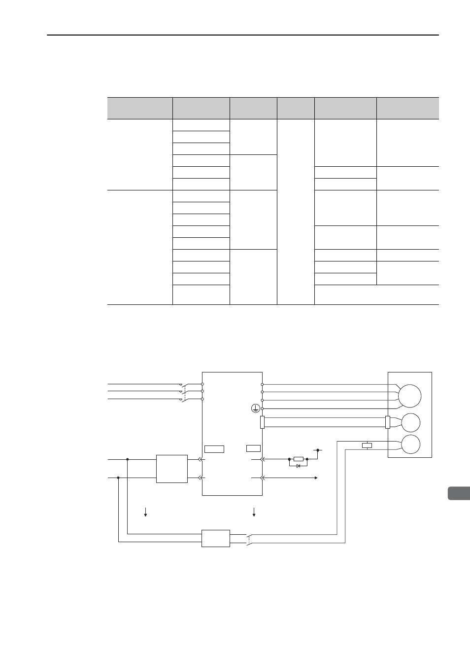
(1) Wiring Example
Use the brake signal (/BK) and the brake power supply to form a brake ON/OFF circuit. The following dia-
gram shows a standard wiring example.
The timing can be easily set using the brake signal (/BK).
Main Circuit Power
Supply Voltage
Servomotor
Model: SGMVV-
Rated Speed
[min
-1
]
Voltage
Brake Open Time
[ms]
Brake Operation
Time [ms]
Three-phase
200 VAC
2BA B
1500
24 VDC
or
90 VDC
500 max.
150 max.
3ZA B
3GA B
2BA D
800
3ZA D
550 max.
320 max.
3GA D
700 max.
Three-phase
400 VAC
2BD B
1500
500 max.
150 max.
3ZD B
3GD B
4ED B
550 max.
320 max.
5ED B
2BD D
800
500 max.
150 max.
3ZD D
550 max.
320 max.
3GD D
700 max.
4ED D
An SGMVV-4ED D servomotor is not
available in a model with a holding brake.
Servomotor with
holding brake
Surge
absorber
Power supply
SERVOPACK and
converter
Red
Black
Blue or yellow
White
M
BK
ENC
U
V
W
CN2
AC
DC
BK-RY
BK-RY
+24 V
L1
L2
L3
(/BK+)
(/BK-)
CN1
CN101
Brake power
supply
AC side
DC side
1D
0 V
0 V
24 V
24-VDC
power
supply
100/200 VAC
400 VAC
+
-
BK-R Y: Brake control relay
A 24-VDC power supply for a 24-VDC brake is not included.
Brake power supply for 90 V Input voltage 200-V models: LPSE-2H01-E
Input voltage 100-V models: LPDE-1H01-E