Yaskawa iQpump Programming Manual User Manual
Page 191
YASKAWA
TM.iQp.02 iQpump Drive Programming Manual
191
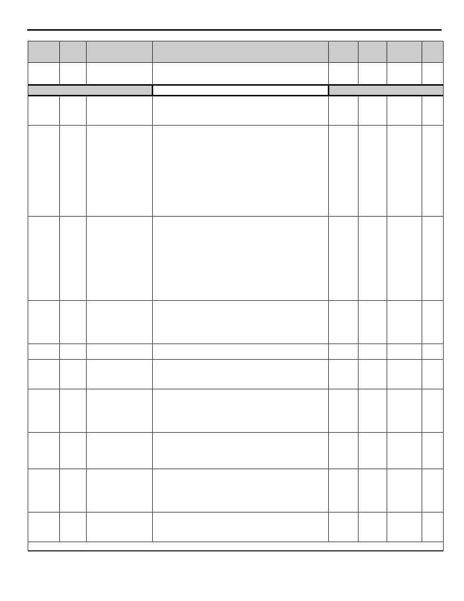
o3-02
0516H
Read Allowed Selection
Read Allowable
Enables and disables all digital operator copy functions.
0: Disabled - No digital operator copy functions are allowed.
1: Enabled - Copying allowed
0 to 1
0
Programming
Pump Basic
P1-01
0600H
Pump Mode
Pump Mode
Select type of control operation.
0: Drive Only (Simplex)
1: Drive + 1 Pump
2: Drive + 2 Pumps
0 to 2
0
Programming
P1-02
0601H
System Units
System Units
0: WC:InchOfWater
1: PSI:lb/SqrInch
2: GPM:Gallons/Min
3: F:DegFarenheit
4: CFM:Cubic ft/Min
5: CMH:Cubic m/Hr
6: LPH:Liters/Hr
7: LPS:Liters/sec
8: Bar:Bar
9: Pa:Pascals
10: C:DegCelsius
11: Ft: Feet
<0032>
12:%: Percent
0 to 12
1
Pump Quick
Setup
P1-03
0602H
Feedback Device Scaling
Fb Dev Scaling
Scaling of feedback device in user units (P1-02=1, e.g. 150PSI).
Digits 1 through 4 set the maximum feedback number. Digit 5
determines the number of decimal places.
Digit 5 = 0: Number format is XXXX
Digit 5 = 1: Number format is XXX.X
Digit 5 = 2: Number format is XX.XX
Digit 5 = 3: Number format is X.XXX
Examples:
01000 = 1000
13000 = 300.0
25000 = 50.00
32000 = 2.000
1 to 36000
(system
units P1-
02)
00145
Pump Quick
Setup
P1-04
0603H
Start Level
Start Level
Drive starts when the feedback level drops below the start level for a
time specified in P1-05. This level also specifies the wake up level
when the drive is in Sleep Mode.
Note:
When PID operates in the reverse mode, the feedback value has
to rise above the start level for the time programmed in P1-05 for the
system to start. A value of 0 disables this function.
0.0 to
6000.0
(system
units P1-
02)
0.0
(system
units P1-
02)
Pump Quick
Setup
P1-05
0604H
Start Level Delay Time
S-Lvl Delay Time
Drive starts when the feedback level drops below the start level for a
time specified in P1-05.
0 to 3600
0 sec
Pump Quick
Setup
P1-06
0605H
Minimum Pump
Frequency
Min. Pump Freq.
Minimum drive frequency when operated in the auto mode.
Programmed value will limit minimum PID output. Minimum value
has to be programmed to a value smaller than P3-09 and P3-10 when
Drive is operating in the multiplex mode (P1-01).
0.0 to
120.0 Hz
35.0 Hz
Pump Quick
Setup
P1-07
0606H
Low Feedback Level
Low FB Level
The Drive will display a “Low Feedback (LFB)” alarm when the
feedback level falls below the programmed level. The alarm will turn
off when the feedback level rises above the programmed Low
Feedback Level plus the Hysteresis Level (P1-13). A value of 0
disables this function. This function is only active during running while
operating in the auto mode.
0.0 to
6000.0
(system
units P1-
02)
0.0
(system
units P1-
02)
Pump Quick
Setup
P1-08
0607H
Low Feedback Level
Fault Delay Time
Low Lvl FLT Tim
e
The Drive will display a “Low Feedback/Water (LFB/LW)” alarm
when the feedback level falls below the programmed level for a time
specified in P1-08. The Drive will coast to a stop when a fault occurs.
A value of 0 disables this function. This function is only active during
running while operating in the auto mode.
0 to 3600
sec
5 sec
Pump Quick
Setup
P1-09
0608H
High Feedback Level
High FB Level
The Drive will display a “High Feedback Level (HFB)” alarm when
the feedback level rises above the programmed level. The alarm will
turn off when the feedback level falls below the programmed High
Feedback Level minus the Hysteresis Level (P1-13). This function is
active during running in the hand mode, auto mode, pre-charge and
thrust-bearing mode.
0.0 to
6000.0
(system
units P1-
02)
155.0
(system
units P1-
02)
Pump Quick
Setup
P1-10
0609H
High Feedback Level
Fault Delay Time
Hgh Lvl FLT Time
The Drive will initiate a “High Feedback Fault (HFB)” when the
feedback level rises above the programmed level for a time specified in
P1-10. The Drive will coast to a stop when a fault occurs. This function
is active during running in all operation modes.
0 to 3600
2 sec
Pump Quick
Setup
Denotes that parameter can be changed when the drive is running.
Parameter
No.
Modbus
Address
Parameter Name
Digital Operator
Display
Description
Setting
Range
Factory
Setting
Menu
Location
Page
No.