I.7 parameter table – Yaskawa 600V User Manual
Page 43
No.
Name
Description
o1-09
Frequency Reference
Display Units
Sets unit display for the frequency reference
parameters and frequency related monitors
when o1-03 > 40.
0: WC (Inch of water)
1: PSI (Pounds per square inch)
2: GPM (Gallons per minute)
3: F (Degrees Fahrenheit)
4: CFM (Cubic feet per minute)
5: CMH (Cubic meters per hour)
6: LPH (Liters per hour)
7: LPS (Liters per second)
8: Bar (Bar)
9: Pa (Pascal)
10: C (Degrees Celsius)
11: Mtr (Meters)
12: Ft (Feet)
13: LPM (Liters per minute)
14: CMM (Cubic meters per minute)
15: Custom units (Determined by o1-12)
16: No unit
o1-10
User-Set Display Units
Maximum Value
These settings define the display values
when o1-03 is set to 3.
o1-10 sets the display value that is equal to
the maximum output frequency.
o1-11 sets the position of the decimal
position.
o1-11
User-Set Display Units
Decimal Display
o1-13
Frequency Reference
and Frequency Related
Monitor Custom Units
1
Sets the customer-specified unit display for
the frequency reference parameters and
frequency related monitors when o1-03 = 3
and o1-09 = 15 as custom units.
o1-14
Frequency Reference
and Frequency Related
Monitor Custom Units
2
Sets the customer-specified unit display for
the frequency reference parameters and
frequency related monitors when o1-03 = 3
and o1-09 = 15 as custom units
o1-15
Frequency Reference
and Frequency Related
Monitor Custom Units
3
Sets the customer-specified unit display for
the frequency reference parameters and
frequency related monitors when o1-03 = 3
and o1-09 = 15 as custom units
o1-16
F1 Key Function
Selection
0: Standard
1: Monitor
2: Drive/Bypass (DRV/BYP)
3: Bypass Run Command (RUN BYP)
4: Toggle Relay Output (RLY)
o1-17
F2 Key Function
Selection
0: Standard
1: Monitor
2: Drive/Bypass (DRV/BYP)
3: Bypass Run Command (RUN BYP)
4: Toggle Relay Output (RLY)
o1-18
User Defined
Parameter Upper
Allows the user to set values that can be
used as reference information.
o1-19
User Defined
Parameter Lower
Allows the user to set values that can be
used as reference information.
o2-02
OFF Key Function
Selection
0: Disabled. OFF key is disabled in
REMOTE operation.
1: Enabled. OFF key is always enabled.
o2-03
User Parameter
Default Value
0: No change
1: Set defaults. Saves parameter settings as
default values for a User Initialization.
2: Clear all. Clears the default settings that
have been saved for a User Initialization.
o2-04
Drive Model Selection Enter the drive model. Setting required only
if installing a new control board.
o2-05
Frequency Reference
Setting Method
Selection
0: ENTER key must be pressed to enter
a frequency reference.
1: ENTER key is not required. The
frequency reference can be adjusted using
the up and down arrow keys only.
o2-06
Operation Selection
when HOA Keypad is
Disconnected
0: The drive continues operating if the HOA
keypad is disconnected.
1: An oPr fault is triggered and the motor
coasts to stop.
No.
Name
Description
o2-07
Motor Direction at
Power Up when Using
Operator
0: Forward
1: Reverse
This parameter requires assigning drive
operation to the HOA keypad.
o3-01
Copy Function
Selection
0: No action
1: Read parameters from the drive, saving
them onto the HOA keypad.
2: Copy parameters from the HOA keypad,
writing them to the drive.
3: Verify parameter settings on the drive to
check if they match the data saved on the
HOA keypad.
o3-02
Copy Allowed
Selection
0: Read operation prohibited
1: Read operation allowed
o4-01
Cumulative Operation
Time Setting
Sets the value for the cumulative operation
time of the drive in units of 10 h.
o4-02
Cumulative Operation
Time Selection
0: Logs power-on time
1: Logs operation time when the drive
output is active (output operation time).
o4-03
Cooling Fan Operation
Time Setting
Sets the value of the fan operation time
monitor U4-03 in units of 10 h.
o4-05
Capacitor Maintenance
Setting
Sets the value of the Maintenance Monitor
for the capacitors. See U4-05 to check when
the capacitors may need to be replaced.
o4-07
DC Bus Pre-Charge
Relay Maintenance
Setting
Sets the value of the Maintenance Monitor
for the soft charge bypass relay. See U4-06
to check when the bypass relay may need to
be replaced.
o4-11
U2, U3 Initialization
0: U2-oo and U3-oo monitor data is
not reset when the drive is initialized
(A1-03).
1: U2-oo and U3-oo monitor data is
reset when the drive is initialized (A1-03).
o4-12
kWh Monitor
Initialization
0: U4-10 and U4-11 monitor data is not
reset when the drive is initialized
(A1-03).
1: U4-10 and U4-11 monitor data is reset
when the drive is initialized (A1-03).
o4-13
Number of Run
Commands Counter
Initialization
0: Number of Run commands counter is
not reset when the drive is initialized
(A1-03).
1: Number of Run commands counter is
reset when the drive is initialized (A1-03).
o4-17
Set/Reset Real Time
Clock
0: — — No Setting
1: Real Time Clock Set
2: Real Time Clock Reset
U1-01
Frequency Reference
Monitors the frequency reference. Display
units are determined by o1-03.
U1-02
Output Frequency
Displays the output frequency. Display
units are determined by o1-03.
U1-03
Output Current
Displays the output current.
U1-06
Output Voltage
Reference
Displays the output voltage.
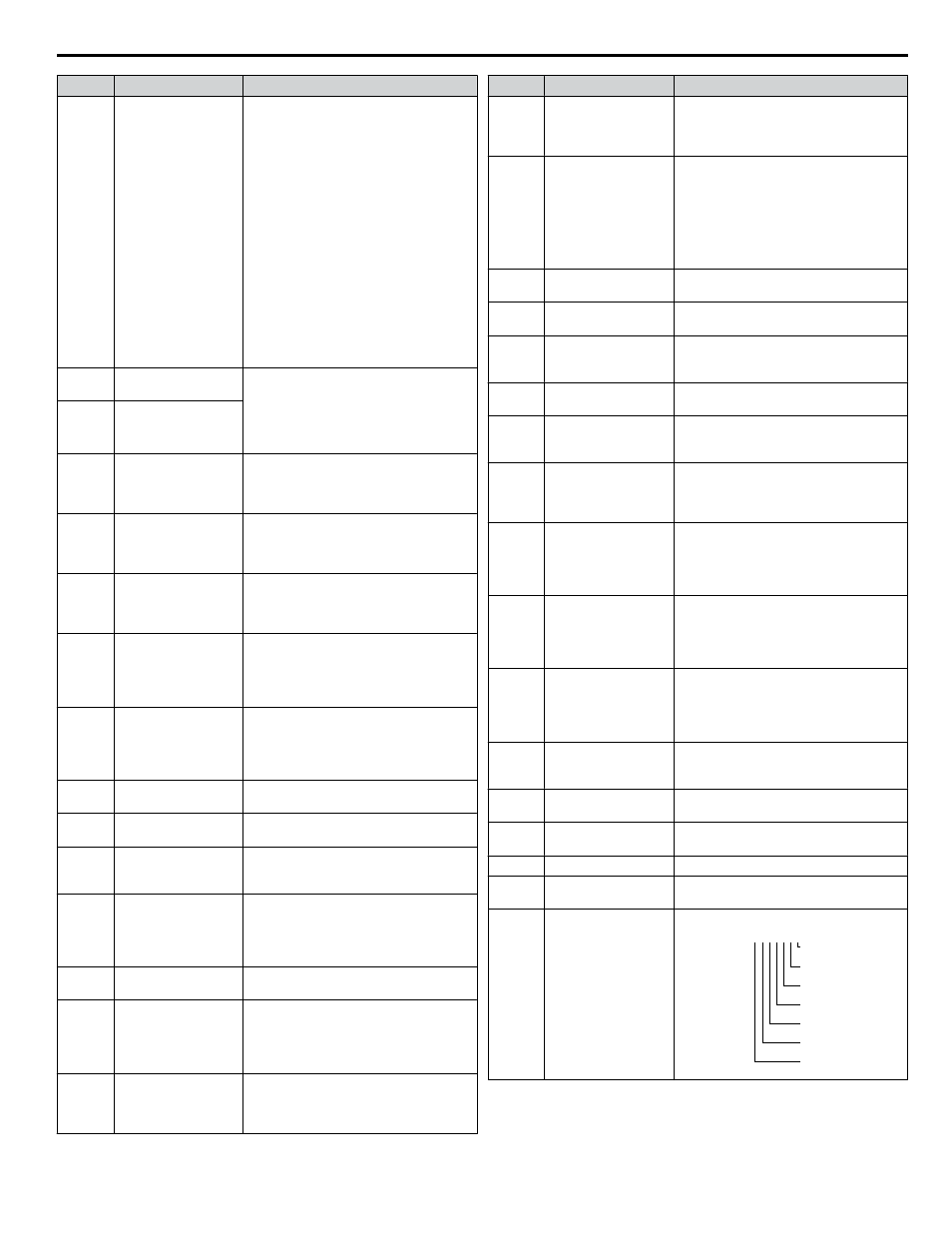
U1-10
Input Terminal Status
Displays the input terminal status.
U1 - 10=
00000000
Digital input 1
(terminal S1 enabled)
Digital input 2
(terminal S2 enabled)
Digital input 3
(terminal S3 enabled)
Digital input 4
(terminal S4 enabled)
Digital input 5
(terminal S5 enabled)
Digital input 6
(terminal S6 enabled)
Digital input 7
(terminal S7 enabled)
1
1
1
1
1
1
1
i.7 Parameter Table
YASKAWA ELECTRIC TOEP YAIZ1U 02A YASKAWA AC Drive – Z1000 Safety Precautions
43